CLASSIC SHIP MODELS 11
Preliminary introduction
HMS "GREYHOUND" 1741
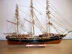
Corel photograph of completed model
HMS Greyhound is a 20 gun 6th Rate vessel of the Royal Navy which was laid down in 1740 at the Limehouse, London, shipyard of Thomas Snelgrove. It was launched in 1741 and served mostly in the West Indies and on the American coast. Little is known about her achievements except that, on one episode, she captured two vessels of similar size and armament. She eventually was driven ashore in the Thames at Erith, Kent, in January 1768 and subsequently declared unseaworthy and sold out of service in April.
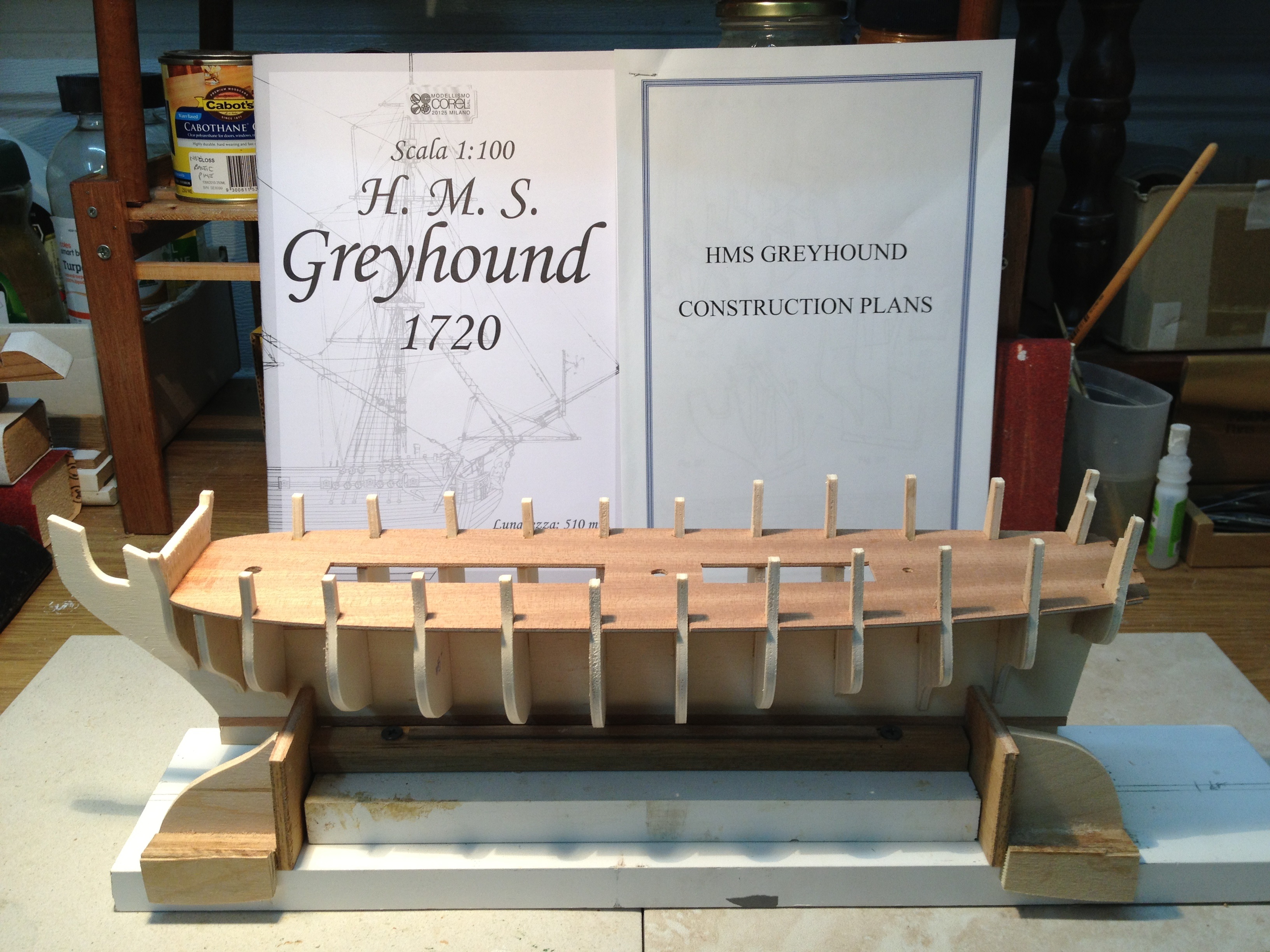
The kit is provided by Corel of Italy, which I have purchased from Gary Renshaw of Modelers Central who now has a large range of various kits - thus making my decision more difficult. This model is of 1:100 and is 510 mms overall - just about the size I was targetting. She is reputed to be a 'good' model to make with a skill level of 3.
This model is said by Corel to have been launched in 1720 but extensive research by Wikepedia report there were around 18 vessels under the British flag named "Greyhound" between 1545 and 1945. There was one launched in 1719 of a similar class to one built in 1712 as was the next in 1741. We are fairly sure the model is representative of the 1741 vessel as she had a career spanning over 20 years whereas the 1719 vessel was captured by the Spaniards in 1722.
The Progressive Construction
Tom Wolf, editor of the magazine "Chatterbox" for the Sydney Model Shipbuilders Club, of which I am an Associate Member, has asked me to provide the club with a step by step progress report of the "Greyhound" for eventual publication. This is a system developed by the club to assist other members, and other readers of the publication, to pass on items of interest or knowledge for the inexperienced.
It seems opportune for me to contribute the same information via my website for those who are kind enough to connect. I am pleased to have viewers contact me for information about model shipbuilding - as I have benefitted over the years from others more experienced than I.
The following pages will reflect the various stages, the problems (if any), the tips and suggestions that come to mind as progress is made during the construction.
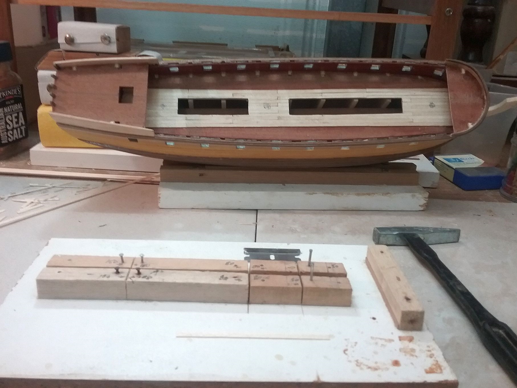
Step one photo 04

The first essential step is to thoroughly check all the material of the kit is complete. I personally then separate all the metal and small timber products into containers with the long lengths of timber remaining in the kit box. Next carefully read the instructions provided and study the plans so you obtain a 'feel' for the model and a broad idea of the sequence of work.
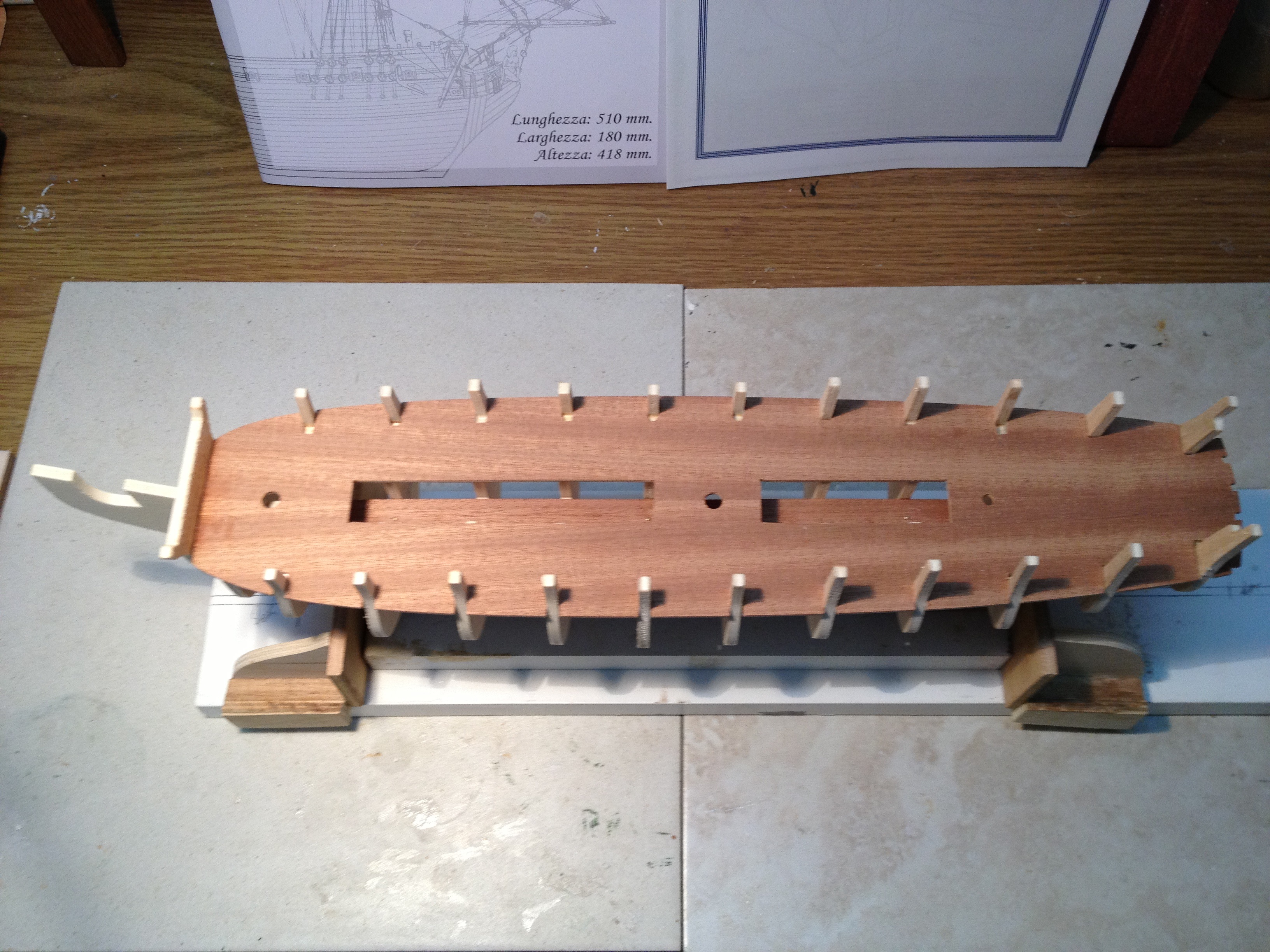
Next, arrange your work bench - removing any clutter or unnecessary tools so a clear work area is available. In this case, I select the pre-cut plywood keel and line it up with my pre-prepared 'drydock' to ensure the keel fits neatly into the 4mm + groove between pieces of 10mm x10mm square timbers which are screwed into a spare piece of board (see photo). This method is often recommended in kit instructions. I also mount this onto a 2nd board containing sliding sections designed to steady the two ends. (Just my preference but not essential).
Step one photo 06
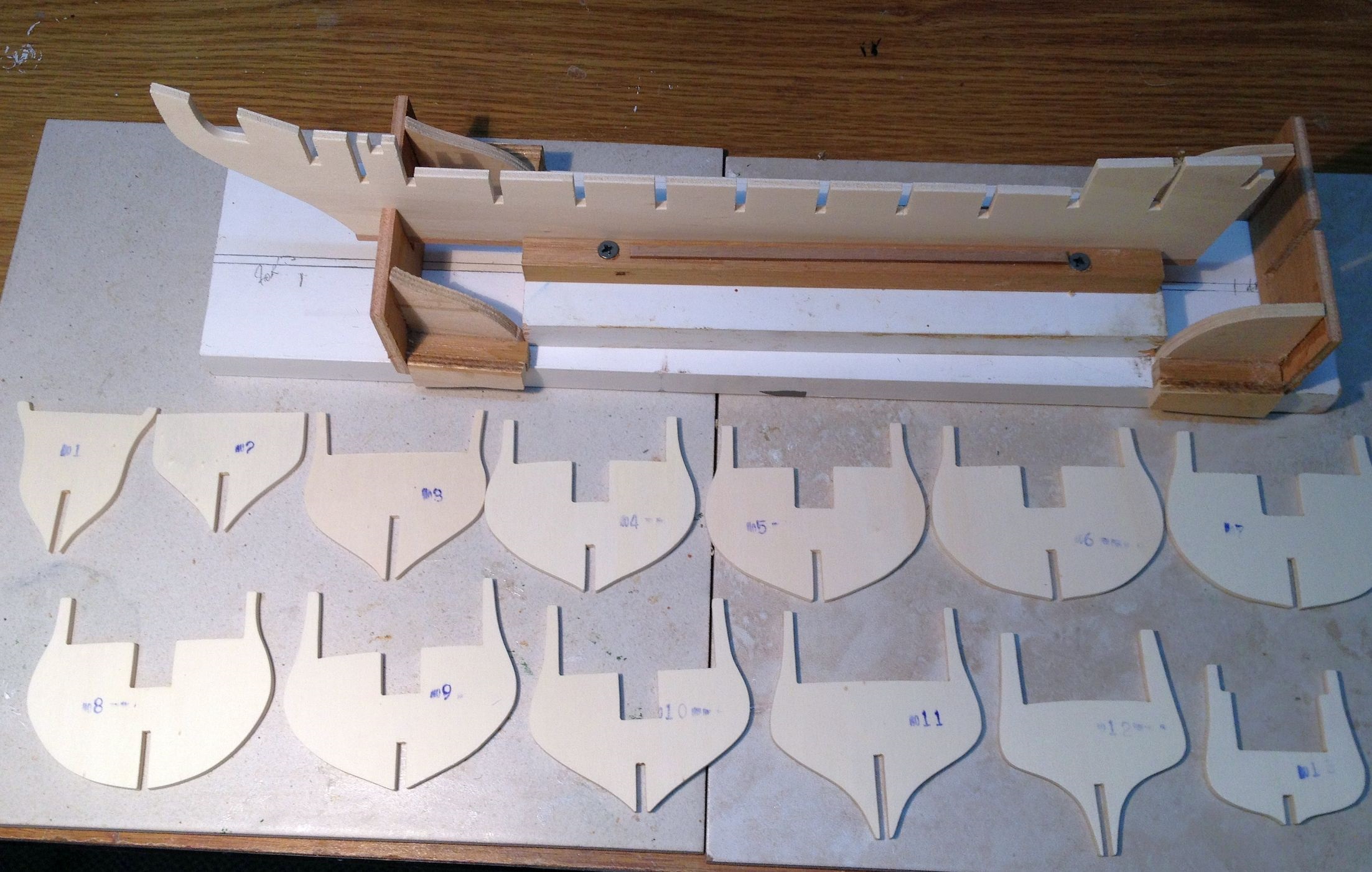
Having satisfied the above, we now lay out all the frames in order of numbering, checking to see if they are clean cut or need light sanding. Then one by one, slot them into their correct positions checking that the fit cleanly, tightly and square. Do not glue them at this stage.
Step two photo 01
This model has a false lower deck which had to be trimmed to fit exactly between the lower level deck in the forrard frames. Do not glue this in until the upper deck is tested to fit. In this case almost every slot in the deck, which should have matched the bulwark supports on the frames, had to be substantially adjusted by filing. It is important to constantly check and recheck to make sure all is in alignment and the keel remains absolutely straight. When all is well, then remove all these components and recommence fitting all the frames, forrard to aft, lightly gluing with aquadhere or similar (not instant) as they have to remain flexible until the decks are in place and they, themselves, are then glued in.
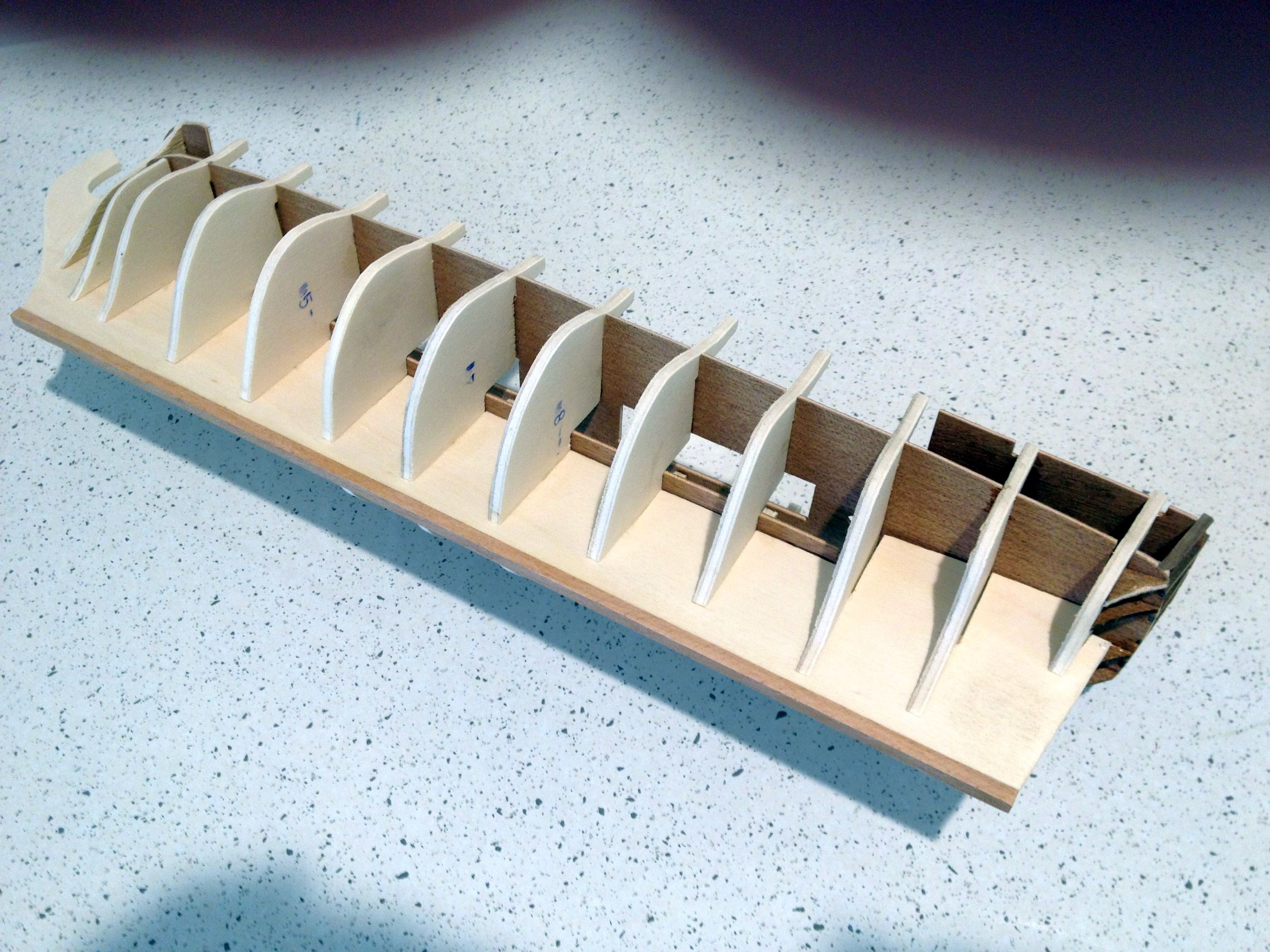
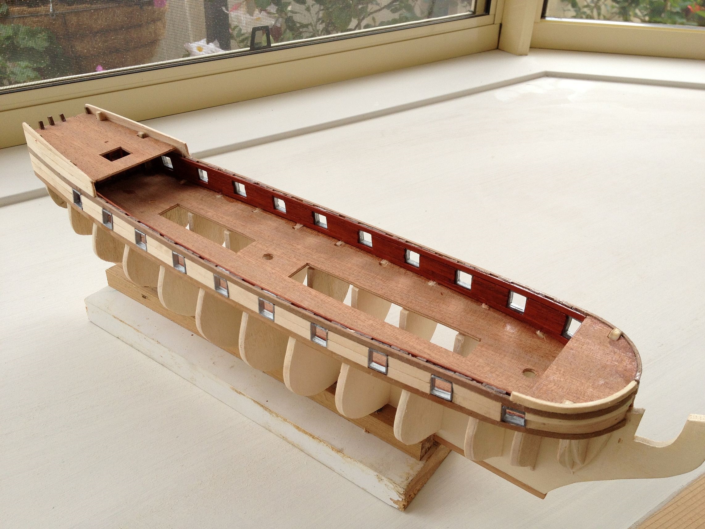
Step two Photo 2-02
Shows all now in place and glued - ready for next stage - viewed from above where the alignment can be best visualised.
Step two Photo 2-04
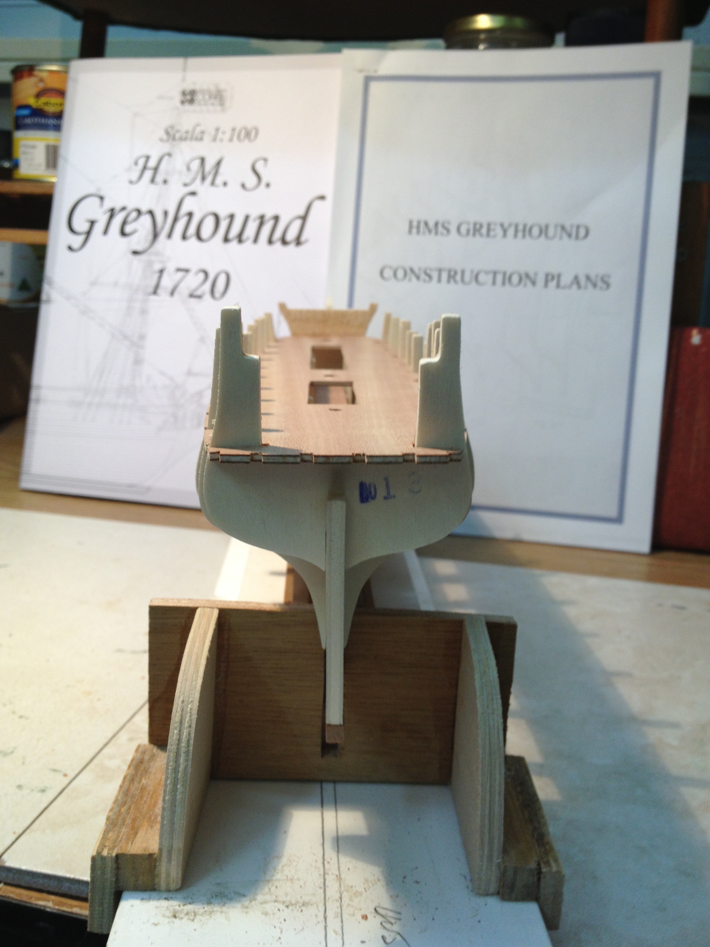
A view from aft also is advisable to ensure the centre of Frame 1 (forrard) is centred with the line of the keel aft. This completes Step 2 and we then proceed with upper decking.
Step 3 Sanding the frames
The first thing in preparing for planking is sanding the frames at forward and after ends to allow planks to be bent to follow the hull shape. Generally this applies to the first three and last three frames depending on the 'lines of the ship'. This photo shows the port side with frames duly tapered.
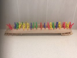
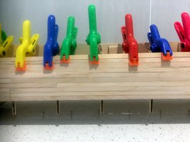
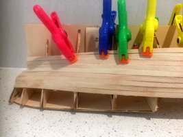
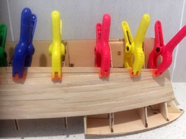
Step 4/01 The first planking
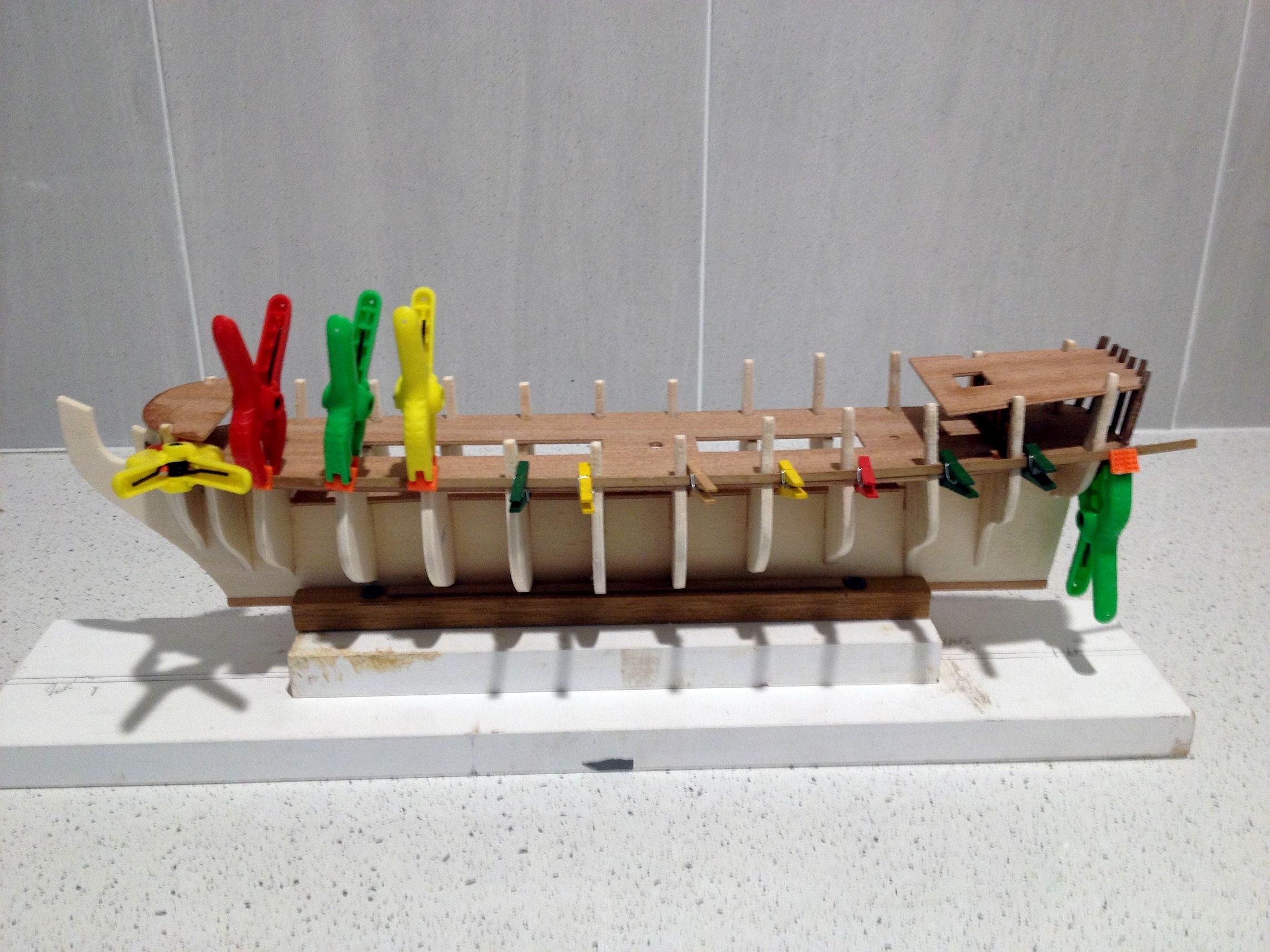
Here we have the first plank (a 1.5x3 mm walnut) secured in plave with clamps and mini pegs. This plank is the lower one of two on each side which will contain the main deck gun ports betwen them. The plank bending, particularly at the bow was done with a steam iron. As the bow bend on this vessel is extremely rounded and the timber quite small, it took a while to achieve the correct angles on both sides without splitting the timber.
Step 4/02 The first planking around the gunports
Now we show the model with gunports secured between the two 1.5 x 3.0 horizontal walnut strips which run from bow to stern. The distance between the two strips was governed exactly by the width required by the gunports. On completion, the external lining with 1.5 x 5.0 mm lime wood strips was inserted horizontally between the gunports.
Before proceeding with the first planking below the gunports, the inboard lining was done. Firstly vertical strips of 1x4 walnut timber strips were laid followed by1x3 walnut sections laid horizontally between the gunport apertures. I chose then to coat the finished internal bulwark linings with a clear water based sealant to protect them. This photograph shows the port side completed with the starboard side awaiting attention.
Step 4/03 First planking internal lining
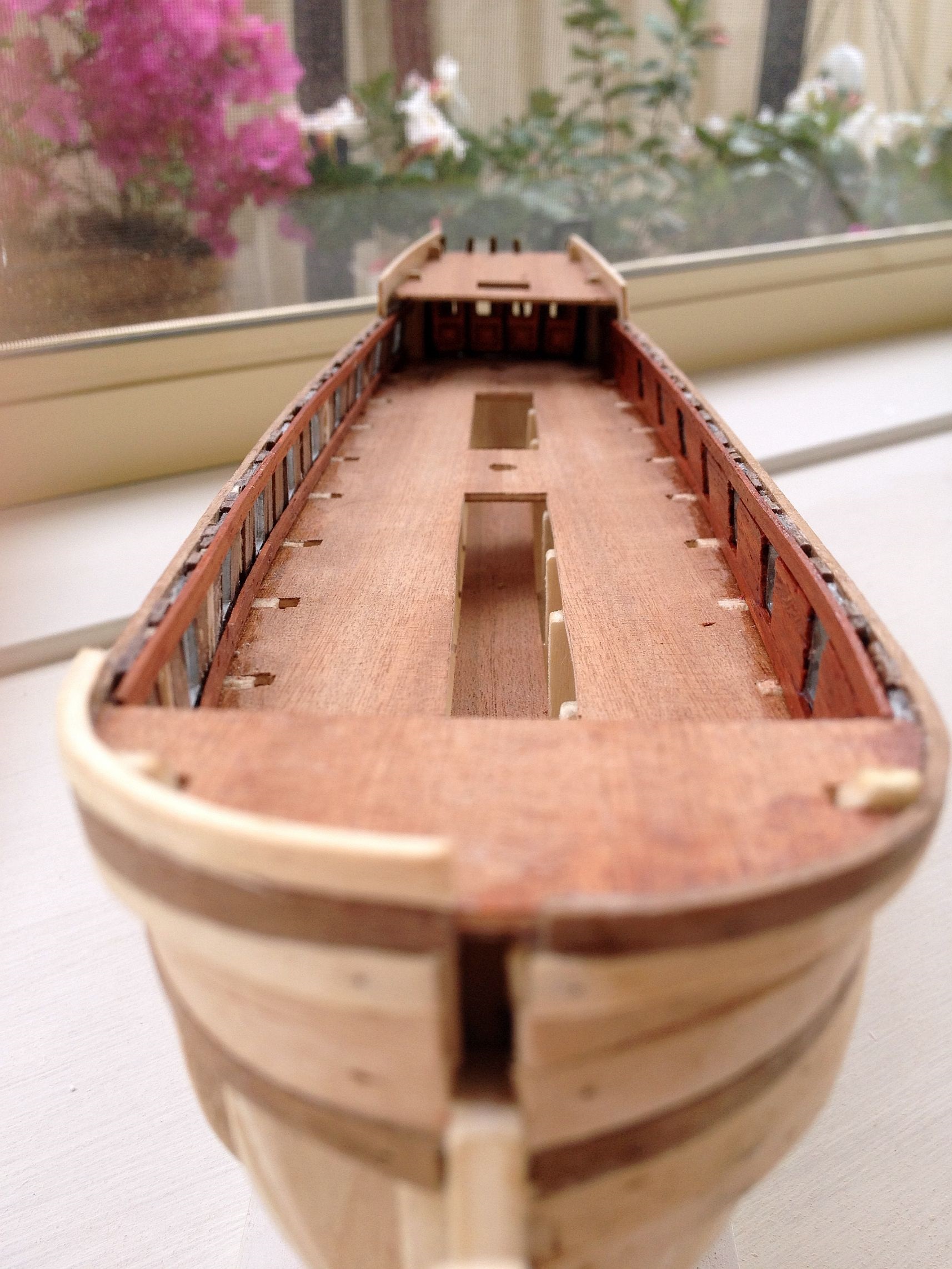
This view of the deckline taken from the bow end shows that the extension sections of the frames have been removed and sanded down to accommodate the deck lining, which will be done later on. As can be seen, the starboard side inner lining only has the top and bottom rails installed and awaits the the fitting of the lining between the gunports. Also noticeable is the bow section with only the starboard side top rail installed with the port awaiting attention! The accurate bending of the 2 x 5mm ramin timber rail, which is glued to the walnut extension of the bulwark, requires a lot of patience and repeat bending under my steam iron before achieving the desired result!
Step 4/04 The first planking complete- view abeam
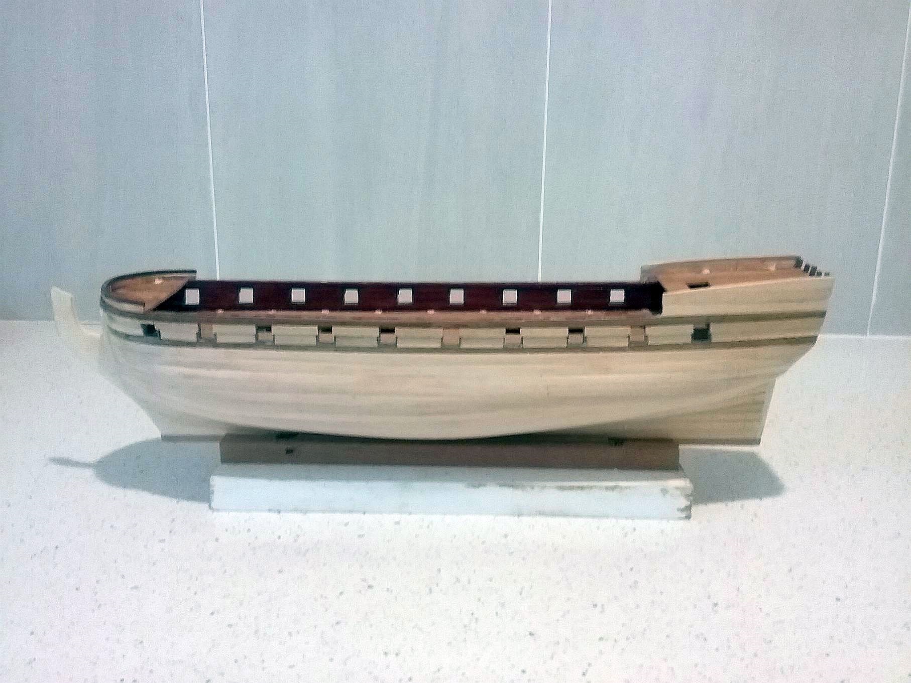
After the 1st planking of 1.5x5 mm limewood has been completed around the gunports and upper structure, I measure halfway down to the keel and secure a plank in that position. I then fill in the planking alternatively above and below that centre plank, bevelling and trimming planks according to how the planks want to naturally bend around the hull. Towards the bow, they need to be trimmed by narrowing them from about the 4th frame forwards. There are ways of measuring carefully how much trim is required but I admit I use my eye judgement and it generally works!
Step 4/05 The first planking complete- view from aft
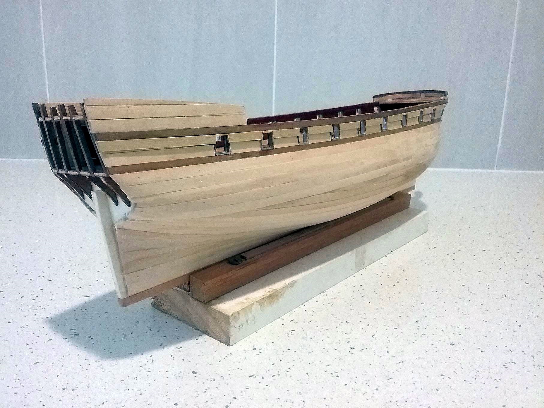
This shows the stern planking and the need to use wedges to fill in the after ends of the pl;anking at the stern. At this stage, the planking around the gunports needed to leave the metal surrounds of the gunports visible. This is rectified later.
Step 5/01 The second planking 01

In this shot, the second planking is well underway. This is where the planking becomes a little more interesting as it is necessary to use varying sizes of timber at various stages. Starting immediately above the tops of the gunports, a 1x3 walnut strake is used covering the top metal surround of the gunports from forrard to aft. Then, between the gunports and from right forrard to aft, 1 strake of 1.5x5 mm limewood followed by a strake of 1x1mm walnut is used to cover half the metal side parts of the gunports. From there, 5 strakes of 1x3 mm bosswood (yellow timber) completes the coverage of the metal frames of the gunports and continues down towards the keel until 3 strakes of 2x2 mm walnut are added. The next stage is the introduction of 1x4 mm walnut which completes the second planking. The photo shows the completion to the beginning of that stage.
Step 5.02 Installing the Decking
With the second planking completed, it is time to coat the hull and the rest of the model with a clear sealant - after painting the required areas in the colours suggested (in this case the yellow ochre). Next on the agenda is to lay the deck planking. This photo shows the technique I use to ensure the planking is uniform throughout. The plans call for each plank to be 8cms in length so the jig is set to produce the required amounts. The timber is 0.6x3 mms, light maple, and the laying commences from a centre line then gradually working out in a brick like fashion ie: staggered and obviously trimmed to shape around the bulwarks and hatchways etc. aquadere is the suitable glue to use as it allows plenty of time to make the final adjustments in placement. The jig shown is self explanatory and quite easy to make. The razor blade used may be 'old fashioned' but is very effective and surprisingly still available for purchase.
5.03 Deck fittings commenced
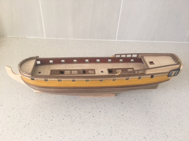
With the decking completed, it's time to start fitting out the the bits and pieces which do need plenty of care as the model is small and so are the fittings! Starting from forrard, the handrail around the bow - according to the kit maker- should be made by making a jig of pins on a piece of timber and using four pieces of 1.0 x 1.0 mm walnut glued together, steamed and shaped within the jig. I opted to use another method using 1.0 x 4.00 mm walnut cut into short lengths with suitably angled sides to fit the shape of the bow. It worked well and much more simple to do. The other handrails on either side needed slight bending as is normal. The photo also shows some of the brass fittings in place including the 'friezes'on the stern rails and the and the side transoms. The hatches now have the gratings made and inserted together with the access ladders to the lowwer deck.
5.04 Painting the transom and side transoms

The transom is always a work of art in these older vessels and this was no exception. The side windows were straightforward but the stern section required a very steady hand and much patience to complete. This one is a little unusual with a variation to the layout and being very small again with very fine molding of the brass figures. The windows were an easier task. Having now reached the tender age of eighty four, I am finding my fingers don't work as well and my eyes soon become sore with too much concentration! However, the results look OK from a short distance away!
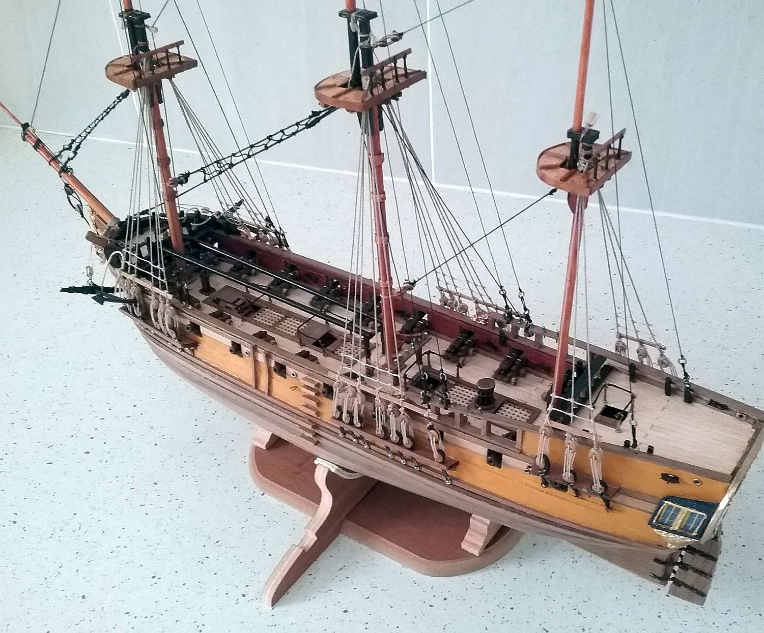
6.01 Deck fittings and masts
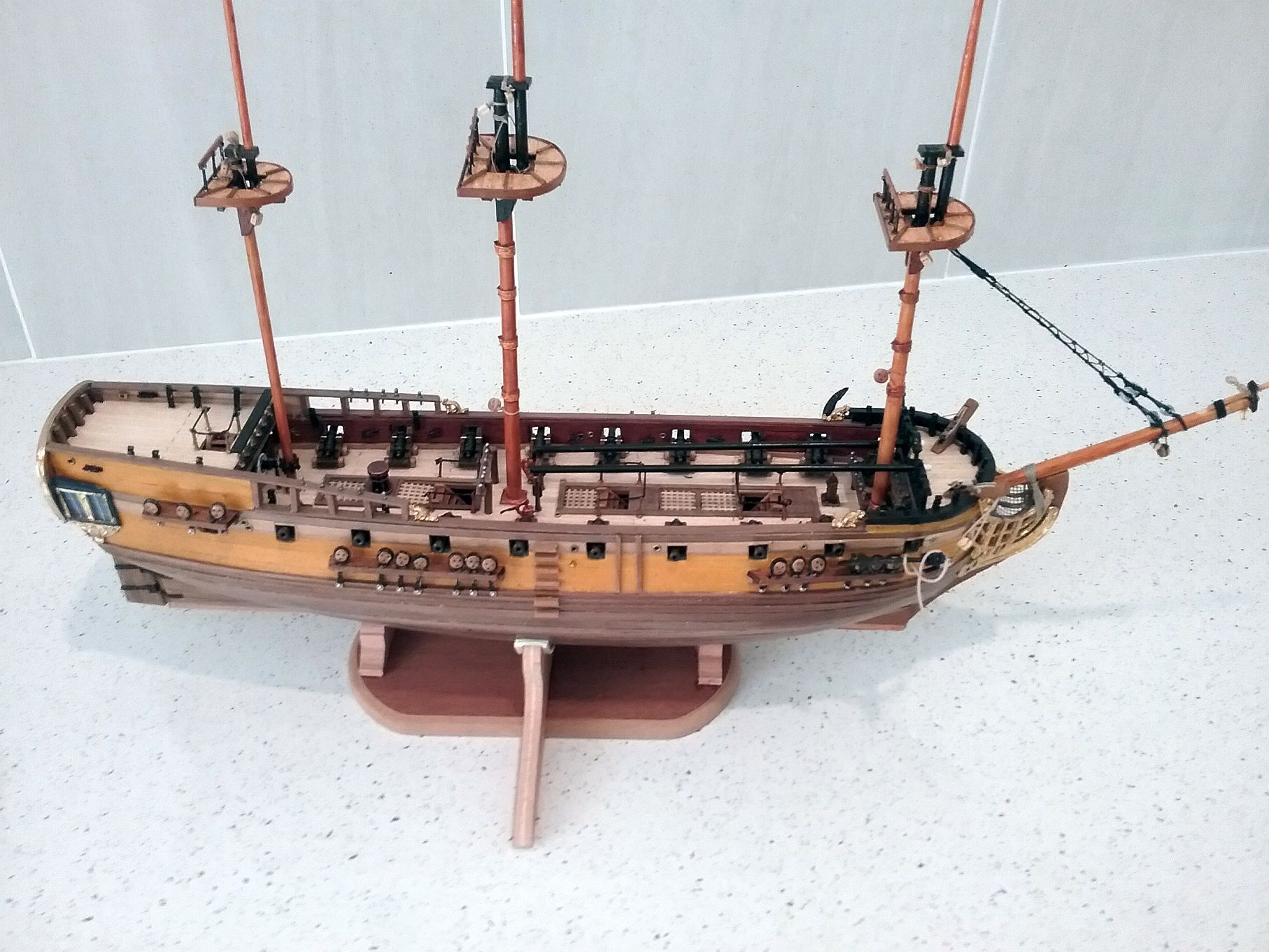
Now you see reasonable progress made since the previous section. The lack of useful information in the intermediate steps can be blamed on poor photographic results - so apologies. Now an improved Samsung tablet is used, so are the results! This first view shows the extent of progress overall. Some close ups follow and the problems faced, the solutions found plus the tips and suggestions be included.
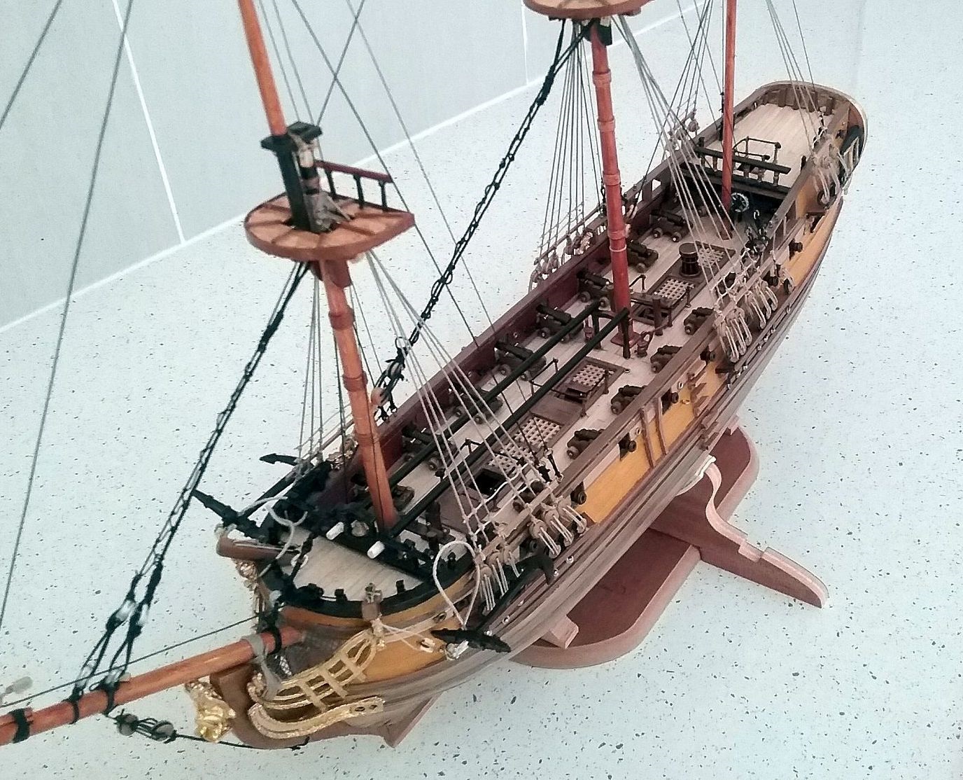
6.02 A view from aft
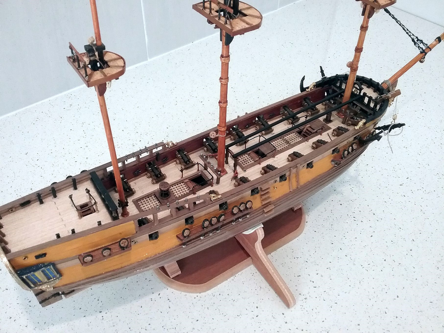
Positive progress has been made with all the deck appliances fitted including placement of cannons, steering fixtures, knightheads, guard rails around hatches, catheads, capstan, water pumps, and the belaying pin racks. On the external hull, the rudder, the chain wales, chain plates, and dead eyes have been secured. The anchors made up have been temporally attached to the catheads - to keep the bow area clear for future rigging.
I found the temporary stand used earlier was unsuitable when the masting commenced so I assembled the more stable unit supplied by the kit maker. The masts and bowsprit, having been fashioned, fitted with crosstrees and caps, plus necessary blocks dead eyes, have been glued in place. Fine cotton was used to provide temporary security to ensure correct positioning until the glue dried.
The tight space around the foremast base is seen clearly in this photo. Two belaying pin racks are sited, one immediately forrard and one aft of the foremast. In addition, a cannon is sited on either side leaving little or no space around them. The ship's bell can be seen mounted on the forecastle deck balustrade aft . Two spare mast/yard timbers are supported above the hatch and the lifeboat is to be positioned on top at a later stage.
6.02 A view from forrard
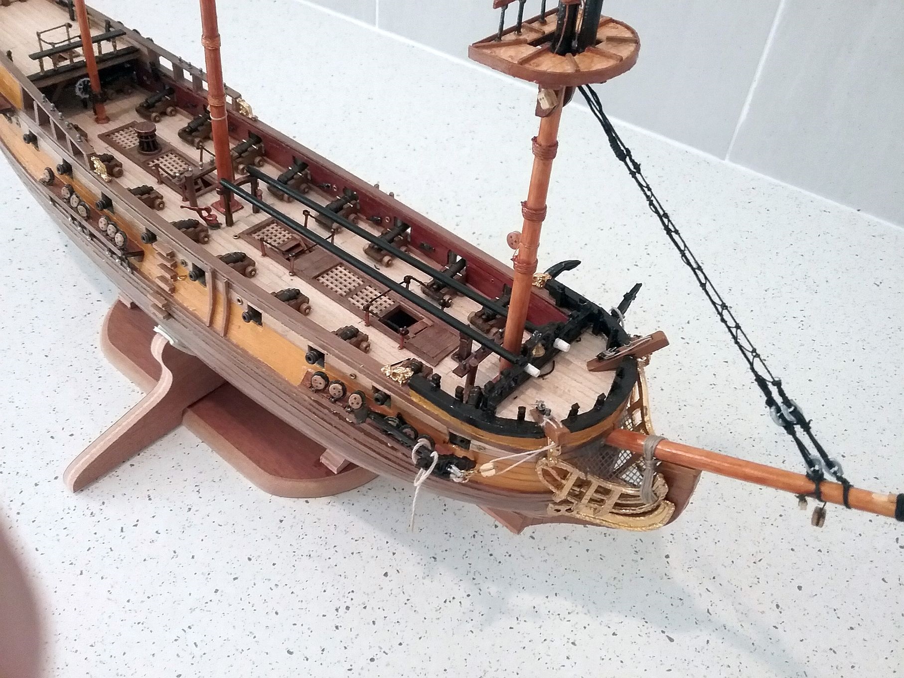
More clearly shown in this photo are the deck fittings. In the assembly and positioning of the cannons, I found it comparatively straightforward except for those under the bow and poop deck. The knightheads, being very small and made of hard leadlike metal, could not be trimmed to fit properly around the bulwarks at variable heights. They, however, seem to sufficiently proud of the bulwark rails to be used as intended.
The two main bowsprit stays are in place (made of 0.5 cotton), joined by a third stay (of 0.25 cotton) intertwined in triangular fashion - a rather delicate operation. Also seen clearly are the rubbing strakes on the starboard side which are repeated on the port, as are the boarding steps amidships.
The position of the ships wheel astern of the mizzen mast leaves the helmsman with little or no forward vision, depending on which side of the wheel he stands! A circular belaying pin rack at the base of the mast further impedes his vision. A cannon is sited immediately behind him, one on either side! I'm glad I was at sea during the 20th century!
Updated 9.4.18
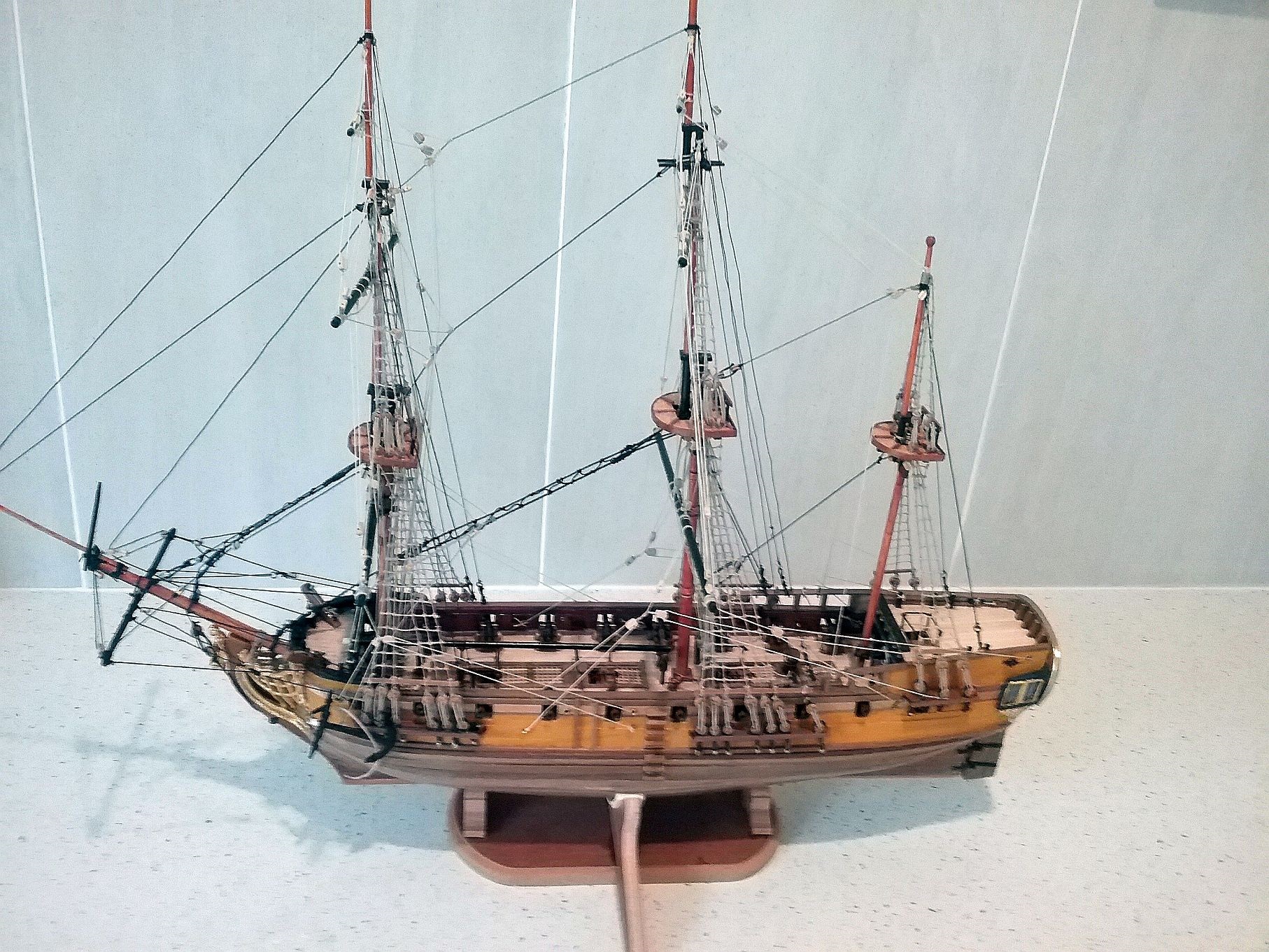
6.03 The standing rigging complete
Having had a relatively clear fortnight of commitments, I was able to spend more time on the model and it can be seen that this was devoted to completing all the stays and shrouds plus the commencement of the ratlines. Apart from the strain on the old eyes, reeving the dead eyes on the shrouds and the fine knotting on the standing rigging as well, I found the securing of the rigging a pleasant task. The plans for the rigging were diificult to follow until I worked out how the designer had documented them. There is a fair amount of cross checking between the instruction sheets and the plans to do, as there is a dearth of photos & drawings.
6.04 Another view of the completed stays and shrouds
Here I show the same condition from a different view. It also indicates the temporary housing of the anchors so as not to interfere with the fitting of the running rigging forrard, as mentioned in 6.02.
Updated 24.4.18
6.05 Twothirds of the rigging complete
This depicts the model now two thirds rigged with all the ratlines complete and the braces etc positioned on the foremast and the main mast. As the rigging progressed, it became more and more difficult to secure the the lines in the allocatted positions - according to the plans/instructions. Due to the small size of the deck areas and spaces between the belaying pins amidships and forrard, it was a task of patience and the use of various sizes of tweezers, forceps and the like.
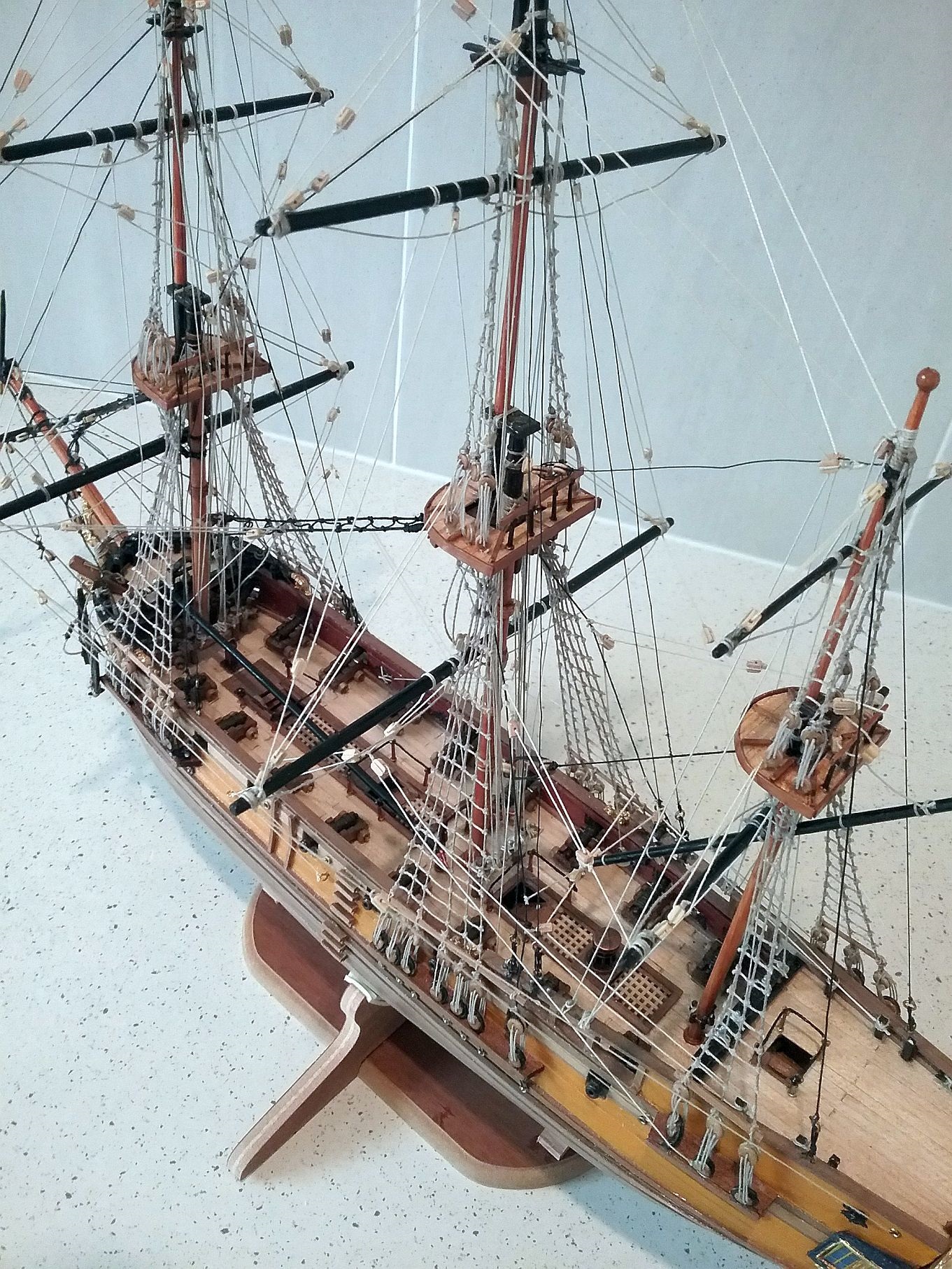
6.06 A view from aft of the part complete rigging
This shows another view of the model taken from aft. It allows a view of the deck where so many of the lines are secured compactly.
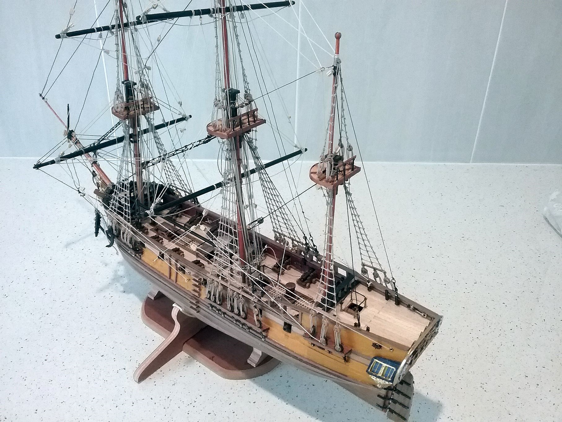
6.07 Rigging completed
Now all the rigging is complete, there are a number of jobs outstanding. The spare timbers over the foredeck hatch , which were moved aside to provide more work space around the foremast, have to be replaced. The lifeboat which was made earlier on needs a few accories made and then the unit to be secured on top of the timbers. Then there are many coils of rope to be made and fitted. The flag staff is to be made and fitted to the poop and the lights attached to the transom. A variety of bits and pieces then need to checked , paintwork touched up as necessary and finally the model glued to the stand.
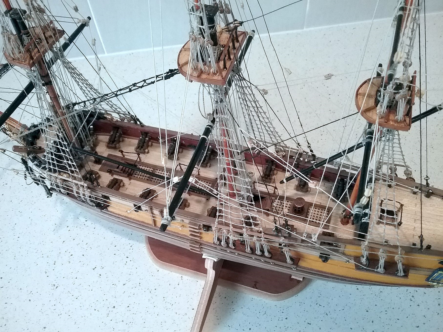
6.08 A closer look from above
This takes a slightly closer look at the complex rigging structure.
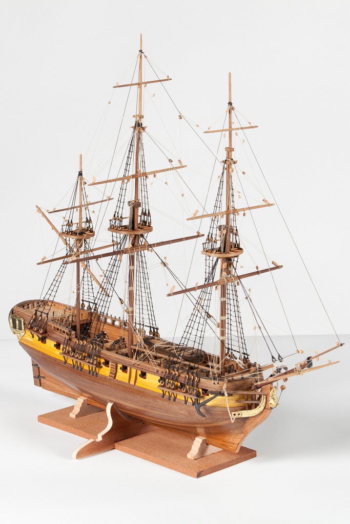
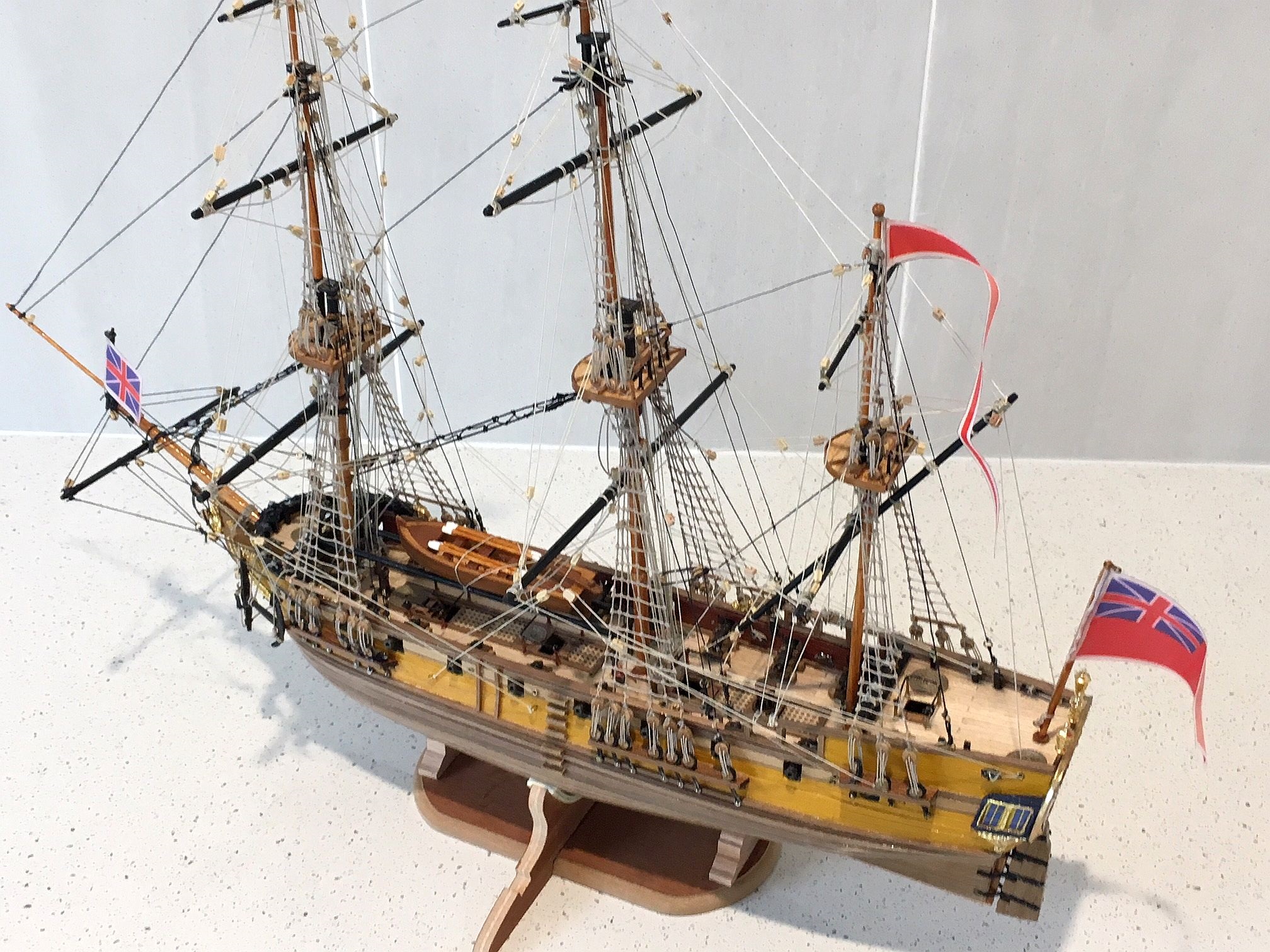
6.09 A Final view of the completed model

Update 24.6.2018
After some six months of toil, the Greyhound is complete. The final touches have beeen made and the flags now fly at the mastheads and on the ensign flagstaffs. Now we await the making of the base plates and the perspex cover which should be available in good time for the model to be displayed at the annual Expo of the Sydney Model Shipbuilders Club on the 18th and 19th of August. All being well, I hope to show 3 models - the Greyhound, the Aurora and one other - yet to be decided. The show is held in the pleasant convention room of the Georges River 16 ft Sailing Club, Sandringham, Sydney, where the Georges river meets the shores of Botany Bay. The displays are available together with workshops and an abundance of advice to potential ship modellers from 1000 hrs until 1700 hrs on the 18th and until 1600 hrs on the 19th.
6.10 Just a second final view
Just another final view of the result of an estimated 220 hrs of enjoyable hobby craft.