CLASSIC SHIP MODELS 13
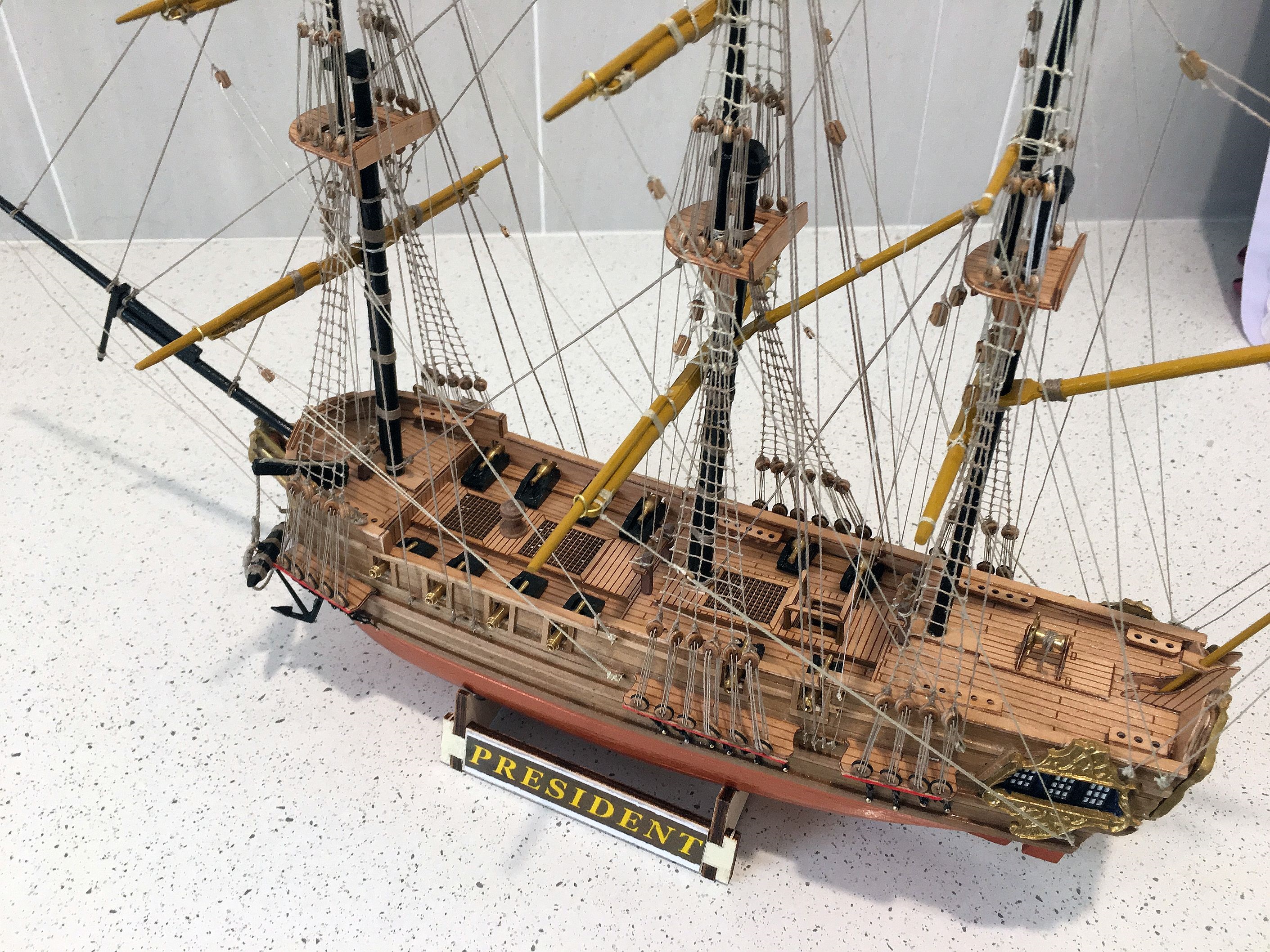
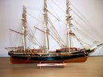
HMS PRESIDENT - a Light Frigate of 1760
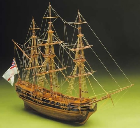
Photo by the kit maker Mantua Sergal
A fine example of a typical frigate built in England in the 1700s. These ships were very fast and manoeuvrable and helped to give the English superiority of the seas during these troubled times. Unfortunately there seems to be an absence of any similar ship's records available in the naval research information available on their websites. As there were numerous battles in this period of the 18th century in European waters as well as the Caribbean and the Atlantic Ocean, between the major shipping powers of that time - Spain, France, Britain and the US - it is not surprising that many are not recorded. A recent assessment suggested there are over three million shipwrecks in the world. Thus it can only be said that this model represents an example of the type of vessel built for the purpose described.
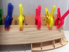
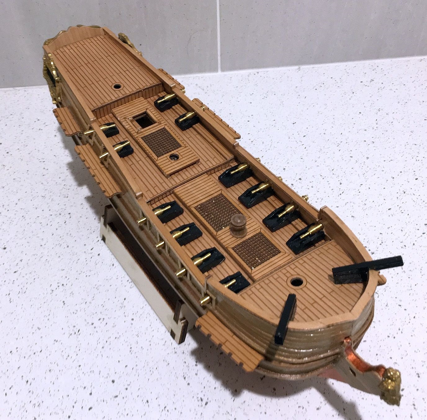
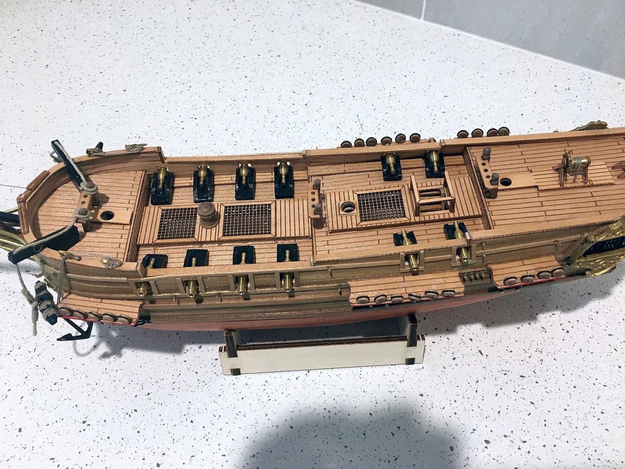
Hull and some deckwork completed
The Model details
The model of the President is made by Mantua Sergal of Italy with a scale of 1:60 with a length of 520 mms. It has a double planked hull and the kit maker supplies a high quality information booklet made up of colour photographs of each stage of the construction as recommended. In addition there is an A3 sheet with diagrams of all the items used from the the keel to the topmasts and rigging.
The early stages of construction was neglected as it was done over a period of three months with other commitments intervening. Hence this was the first time photos were taken of progress - after the hull, decking and some fittings were completed. It was commenced in March 2019 and this and the following two shots were taken on May 31st.
A number of issues were overcome in the period which are mentioned in the next two text sections
Deck from above and astern

A few observations during the construction to date
Framing
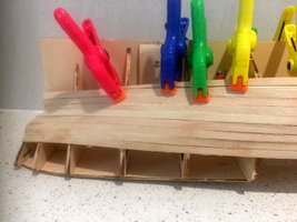
The laser cut frames were of high standard and required very minor sanding to obtain accurate fitting The strengthing members were similarly easy to fit. The suggested order of work then required the laser cut deck sections to be fitted and this was followed with perfect fitting. In hindsight, however, it would have been more sensible to cut in the gunports first as it was very difficult to drill the apertures without damaging the deck - as the lower part of the hole was but a millimetre or so clear of the deck level. Obviously the recommended time to do this - being much later - was to ensure the accuracy of the position.
Hull material
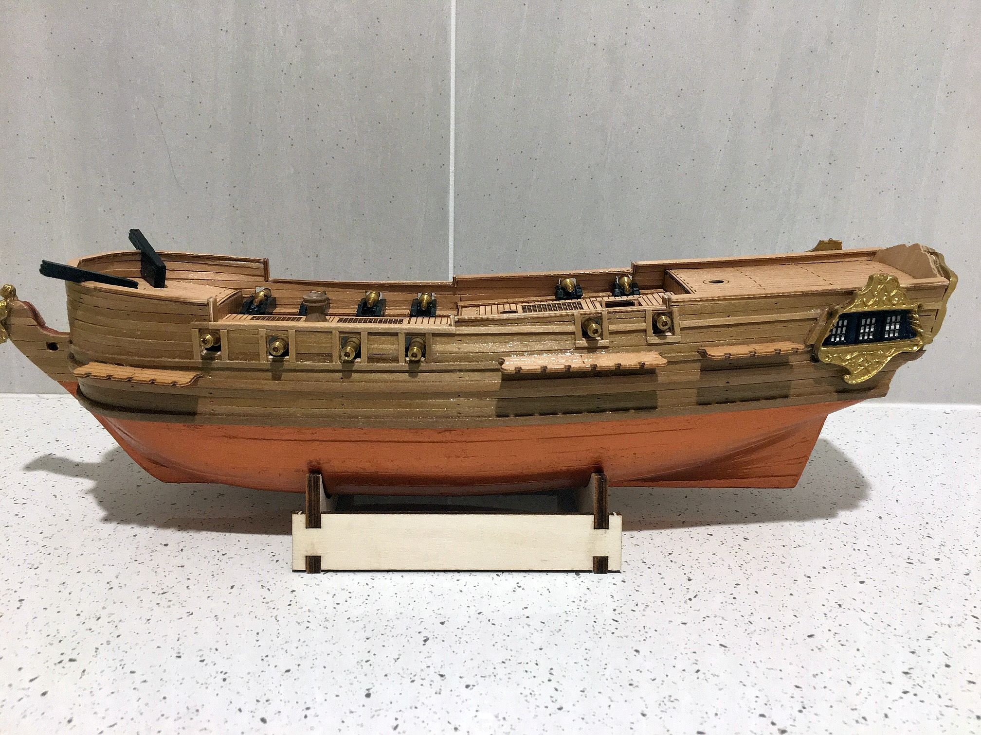
The hull below the waterline could be either sheathed with copper plates (which were not supplied with the kit) or painted in copper colour. Option two was adopted due to the relatively small size of the model and the size of copper sheeting available in stock was too large to use.
Deck from ahead and above
The deck fittings
The design included laser cut sections to be glued along the inside of the bulwarks, over the top of the normal deck level, with protrusions indicating the position of the carronades in line with the gun ports. When the time came to fit the guns, it was found those on the after deck (4 in number) were too high. Consequently, modifications to those carriages were necessary. Overall there were a number of areas where measurements of the model did not completely concur with the photographic material supplied. As an example, a 5mm hole was shown as being made in the bow to take the bowsprit which, if done, wiould have speared the deck. The A3 drawing of the bowsprit area showed it at a far greater angle than that in the colour photo! The hole was drilled 4mm lower!
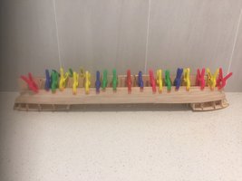
The other feature was the time of securing the channels. It woud have been better to await their application until all the work around the outside of the hull had been completed, instead of well before! Any job that needed the ship to be laid on it's side does not need to have the channels taking any weight. More personal forethought should have been applied!
The above comments are not intended to be critical of the design but rather to indicate that there are often examples of minor differences between the model makers product and the one designed and made by the professional kit makers.
The Transom
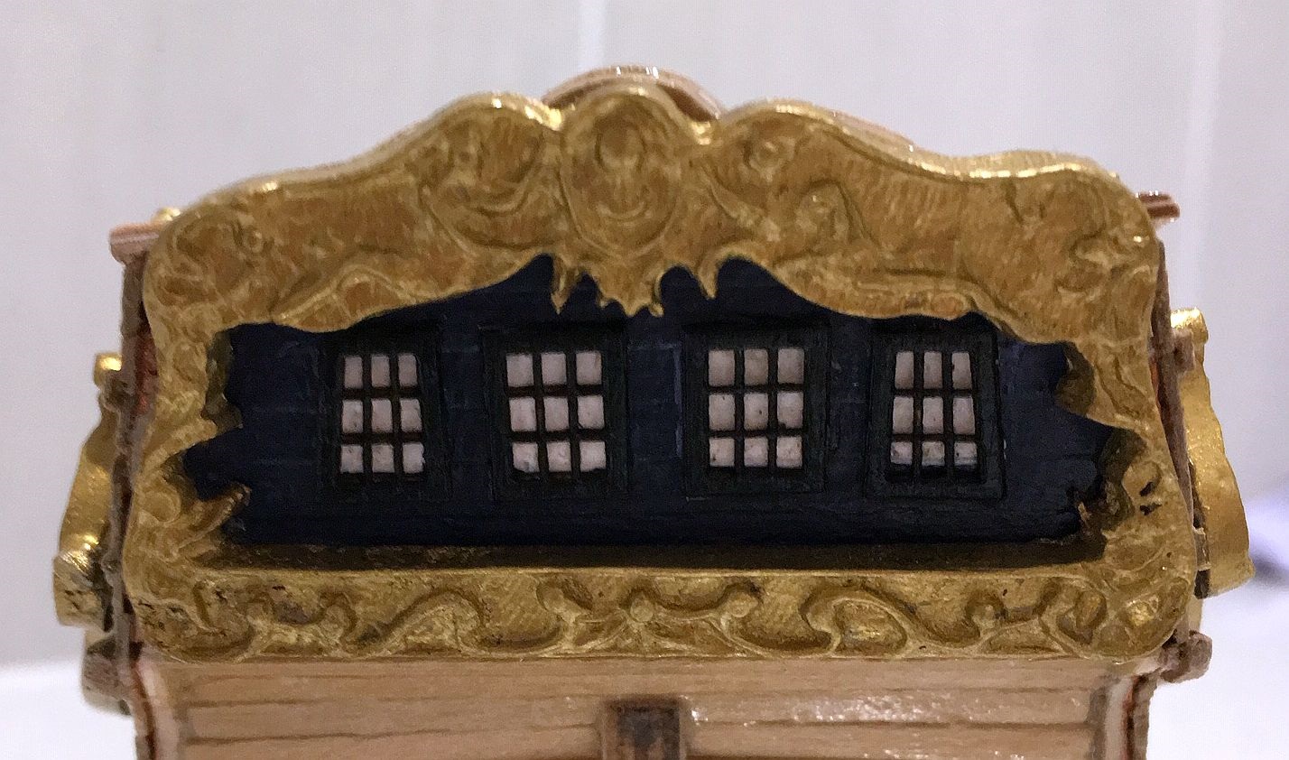
Fitting the gilded sections
Before the gilded transom was glued in place, it needed some intricate and accurate painting prior to appling the laser cut 'mini' windows. Firstly the side windows and the transom gilded sections had to set in position and pencil marked on the hull timbers showing the external and the internal shapes. Then they were removed and the window shapes etched in. the window areas were painted in white and the surrounds (out to the edge where the of the internal areas) in blue. When sufficient coats had been applied and the juggling needed to be as accurate as possble, the gilded sections were glued in. Finally the each window was individually placed to cover the relevant white painted area. A painstaking job at the best of time!
Overview of progress
Fitting out the hull attachments 1
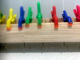
After finalising the rest of the deck fittings - the steering wheel and attachments, the capstan, the flag staff astern, the belaying pin racks and the protection rails around the access hatch - attention was moved to the dead eye assemblies on the previously secured channels. Being extremely small, the dead eye straps, which consisted of three separate parts, took time and patience. The thirty of them took around 30 minutes each on average to ensure they holding firm and at the right angles.
View from forrard
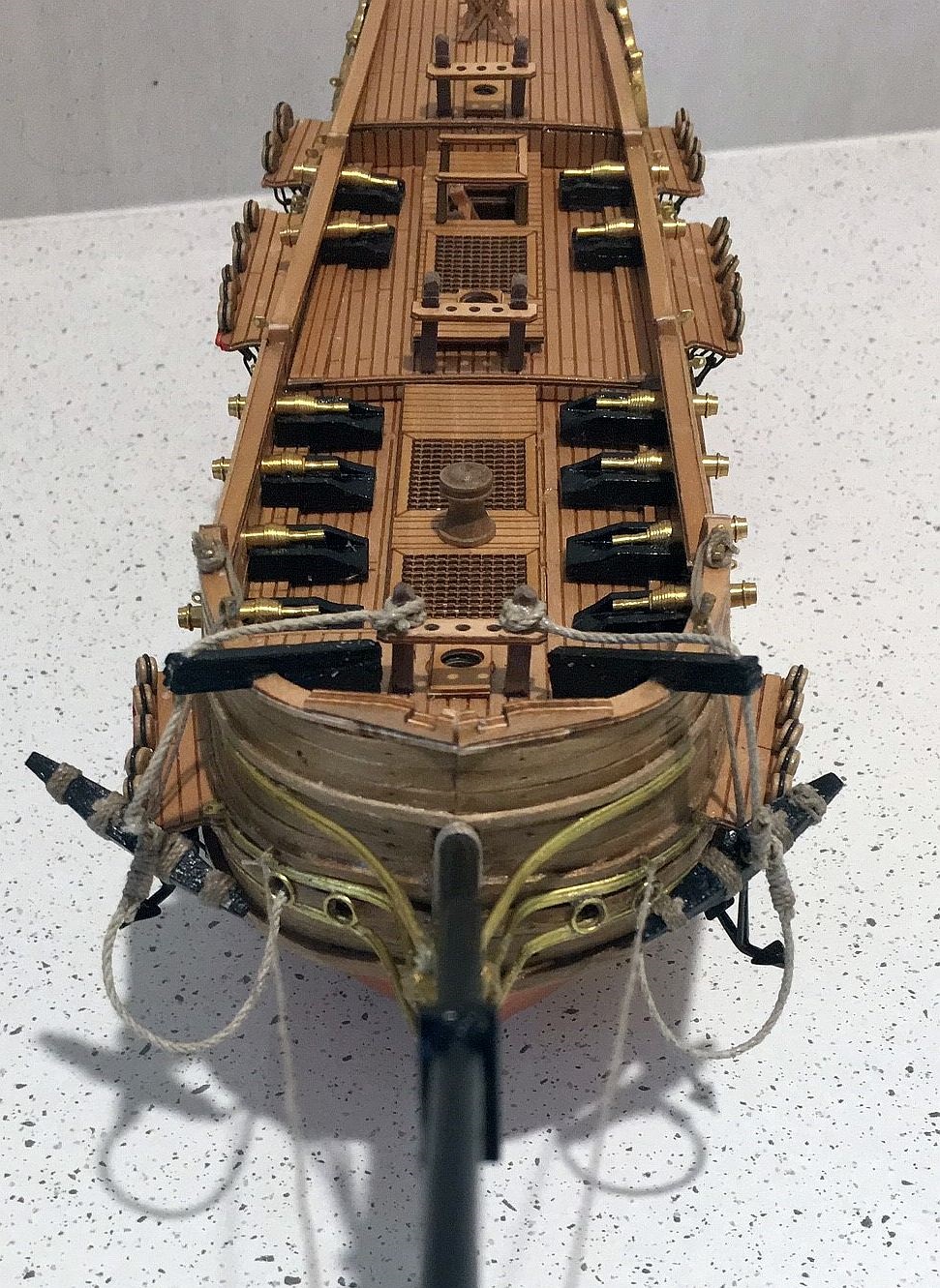
Fitting out the hull attachments 2
Moving then to the anchor assemblies, it was noted the instructions had the anchors held against the hull by hanging a fluke on the channel between the first and second dead eye. It was considered to be more practical to hang them off with ropes from the stock through a fairlead on the bulwark and secured to cleats on the bulwark. It worked well although neither the fairleads or the cleats were suppplied. They came out of personal stock!
View from abeam
Fitting out the hull attachments 3
Altogether there were 36 pintles to attach to the hull before any of the rigging and masting could proceed.This left just the assembly and fitting of the bowsprit, the gammoning and first of the rigging from bowsprit end to the pintles on the bow.
Updated 22.7.2019
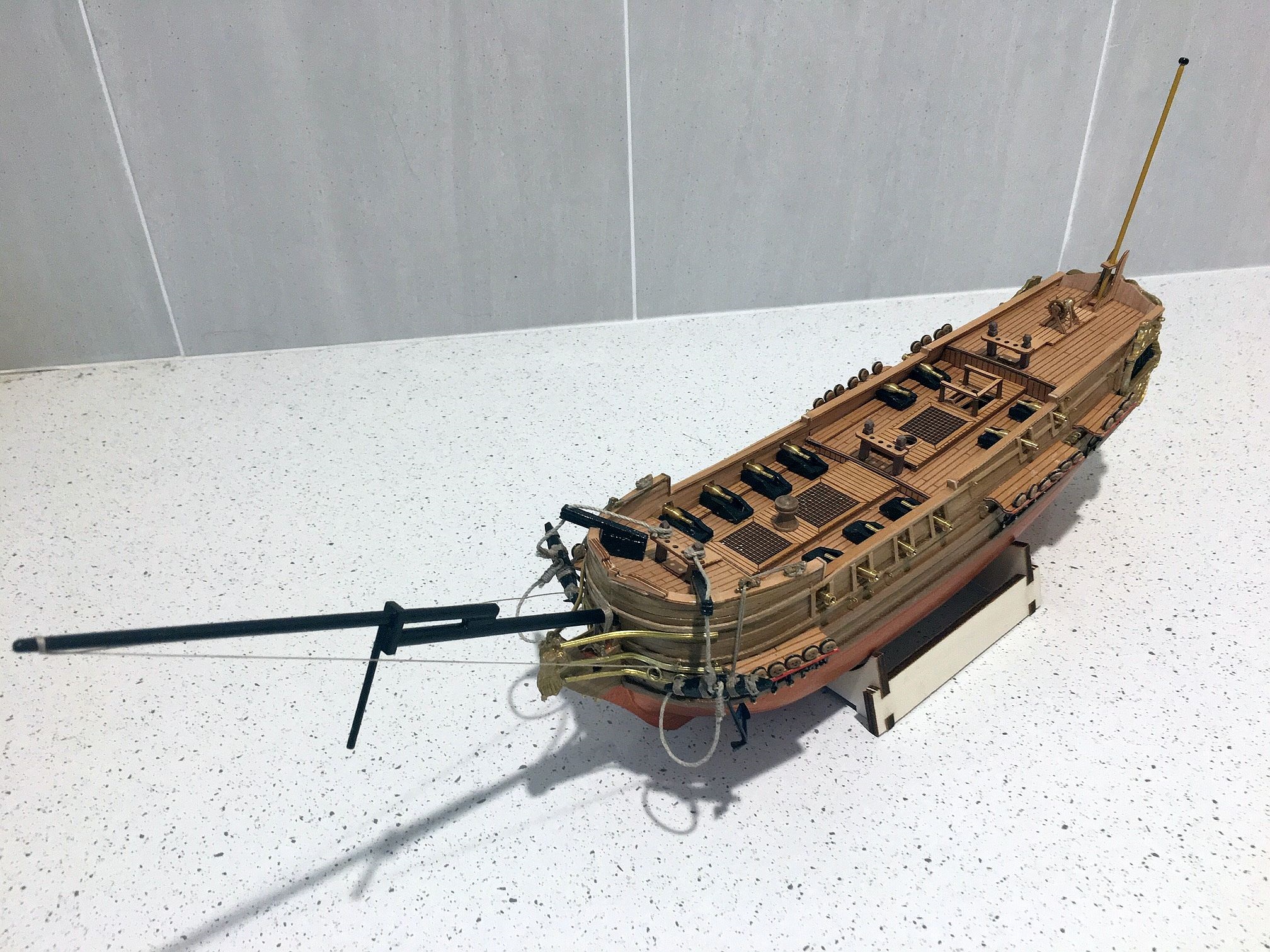
Preident complete - side view
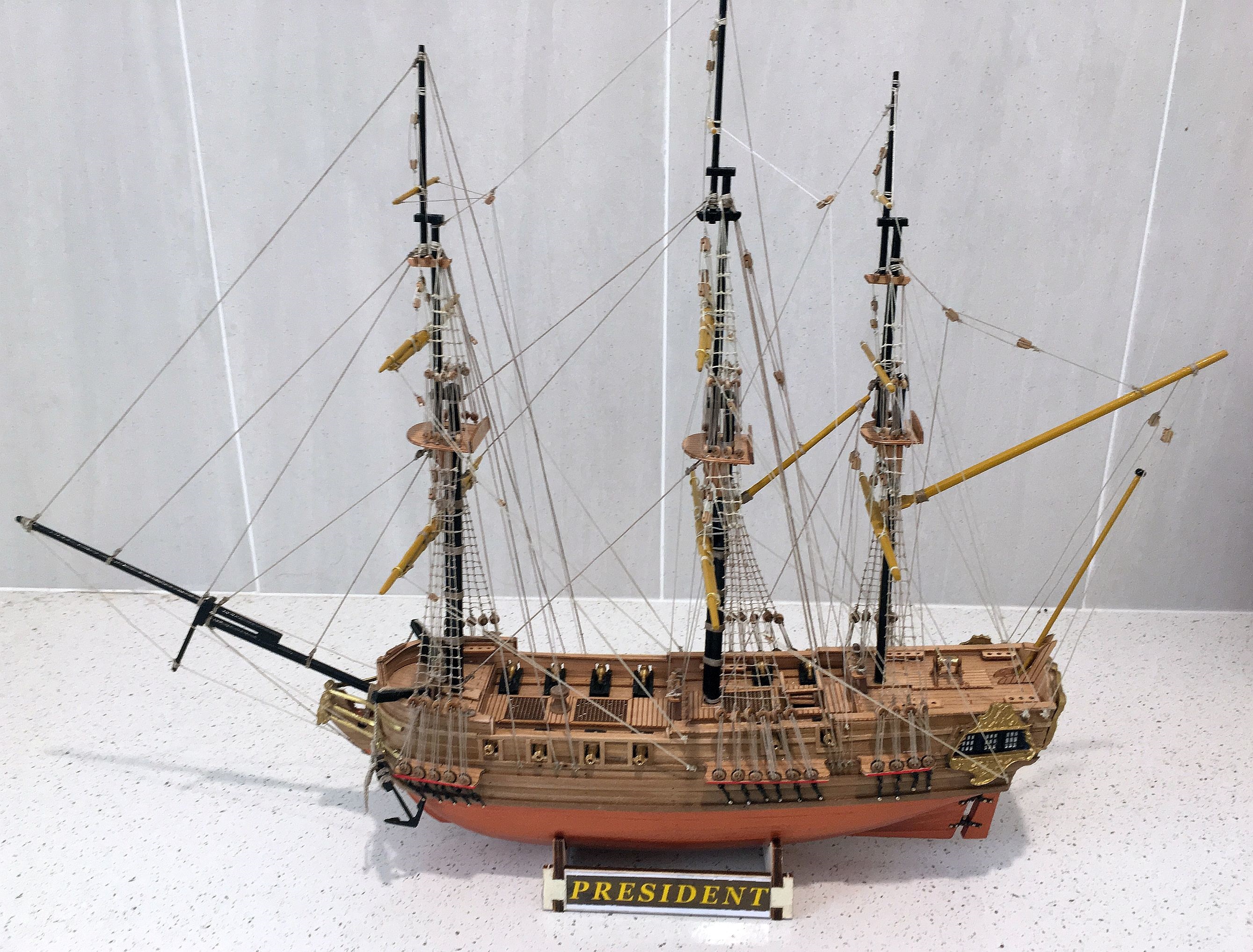
Apart from the the final touch-ups, at long last HMS President is complete. The model will now be shown at the Sydney Model Shipbuilders EXPO in Sandringham, Sydney NSW next Saturday and Sunday August 25 and 26.
Overview of rigging
Although a relatively small 12 gun frigate, the rigging was just as complex as the larger models. In fact, due to its size and the that of the cottons reuired to be used, the threading of 3mm blocks with 0.25 cotton needed a steady hand and very good eyes. Having now reduced vision and some trembles of the fingers, progress was slow! The following two photos show different aspects - with the second giving a closer look at the rigging.
President complete,elevated view
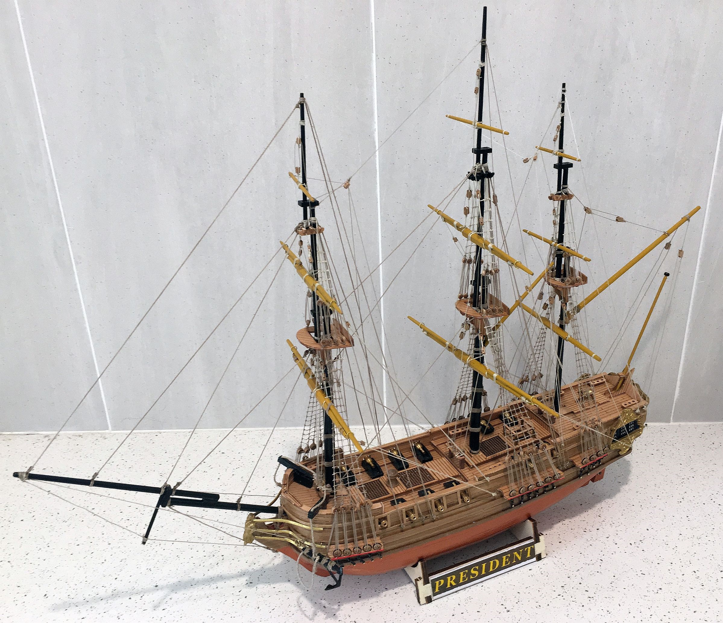
All that remains is to add the ensign, coil a few ropes on deck and have a general tidy up.
There are two more models awaiting attention but me-thinks a short break is in order!
Updated 19.8.2019.