Classic Ship Models 16/2
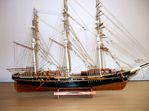
Mercator No 2 construction details
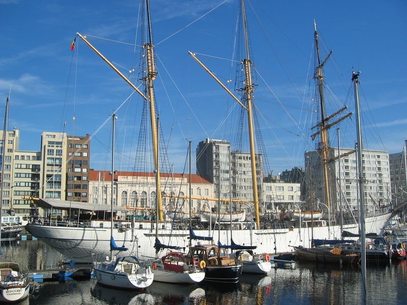
'MERCATOR" IN Oostende Harbour.
where she is a Museum piece
With the completion of Classic Ships No 25, a short break from model ship consruction was desirable. Hence spare time was occupied putting together a balsa frame model of a Spitfire for a Christmas gift to an appreciative great grandson.
Finding the energy to start anew, the internet was browsed and my attention taken by Modellers Central Black Friday special offers for some of their kits. Amongst them was the "Mercator". That ship was one of my very favourites to make and to view. However, recently it was passed on to a very good friend and his wife who had similar views! Not finding anything else that appealed, I secured the kit and now have just commenced the build.
Unlike the previous model, I will record the various stages of construction as they occur. As with the previous model of Mercator 1, balsa wood will be used for the first planking and the second planking will have the walnut timber as supplied in the kit.
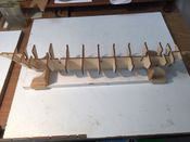
Keel and frames in position
The frames needed some fine tuning by light needle filing which resulted in an excellent tight fit of every frame.

Lower deck being prepared to fit between frames
The 'spine' of the model is a full length lower deck line fromforrard to aft with over thirty 'cuts' to fit ove the frames. These required a patient and extensive fine tuning with the needle files, making sure too much was NOT taken in so doing.
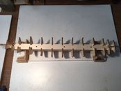
The Lower Deck in place, tight and awaiting to be glued.
After much too-ing and fro-ing, the spine was fitted without incident but care was taken to avoid breakages of the comparitively delicate section.
Glueing of these components has to be made after this fitting is finalised.
First 2 planks in place Port side
The first planking in balsa wood extends from the bow to a position on the stern where vertical planking in walnut was required. This shows the port side using the clamping method best used for these first two planks.
First two planks on starboard side in place and glued
This shows the two planks completed and glued on the starboard side whilst the port side awaits the drying of the glue.
Counter stern design includes vertical planking
Here is shown the vertical planking on the stern which is required to create the shaping of the counter stern
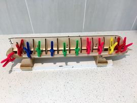
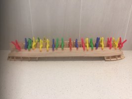
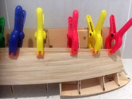
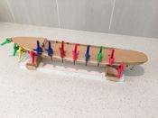
Upside down clamping of 1st planking
As the first planking is done with balsa wood - it being very soft - one tries to avoid the use of pins as much as possible. Thus, wherever possible, clamps are the better prospect. This applies here to the third row onwards.
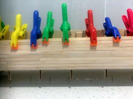
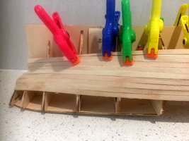
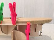
Close up of upside down clamping
This shows the upside down clamping which can be used, in this model, until the clamps can no longer have access. Note: pins have been used, as well as clamps in the forrard and after ends.
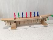
Profile showing completed 1st planking
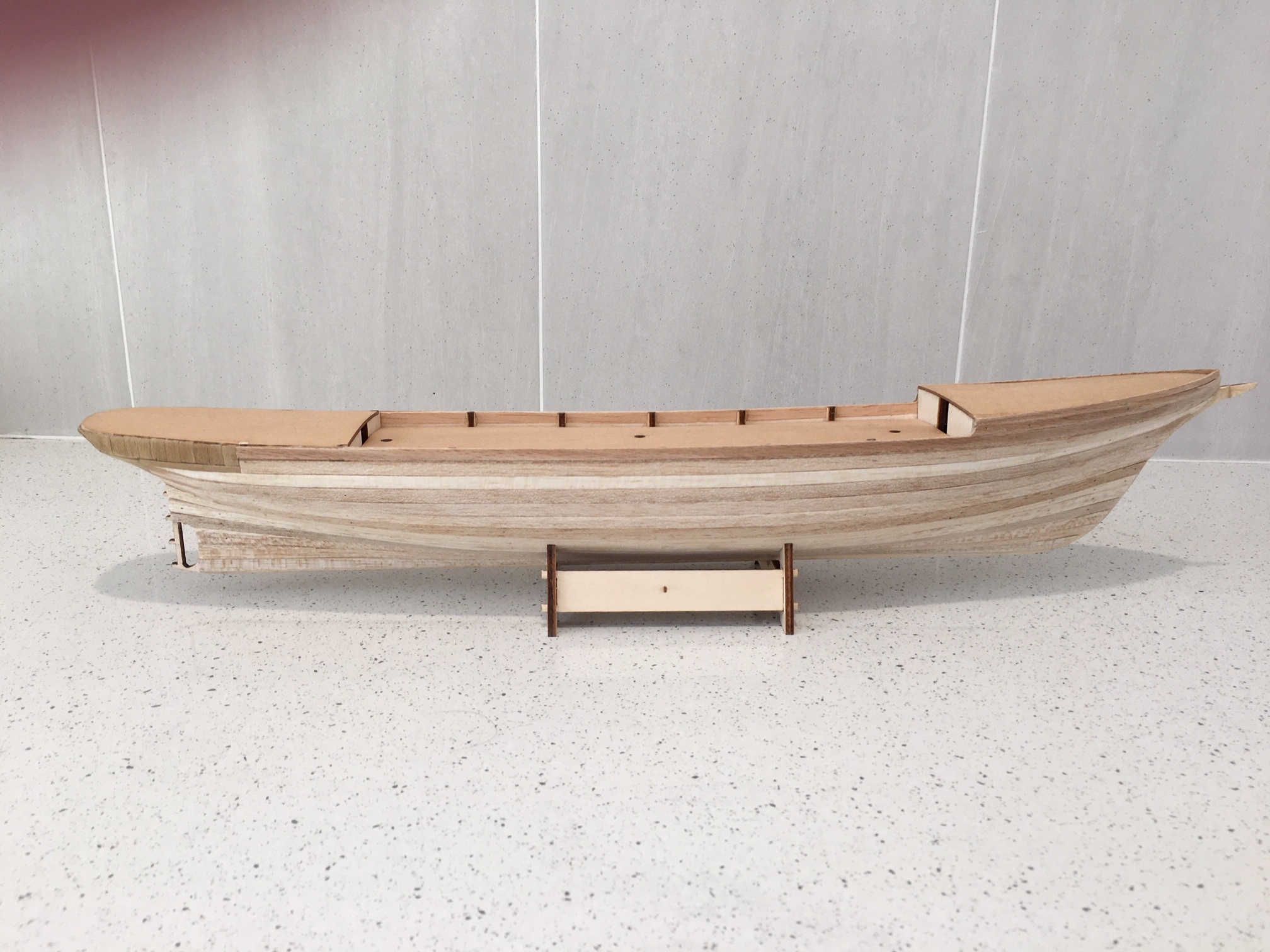
The 1st planking was completed on 26.1.20 and the first of the second planking added. Using walnut 4mm x 1mm timber, the first plank was affixed using a combination of clamps and pins. Thereafter only light pinning and glueing will be used.
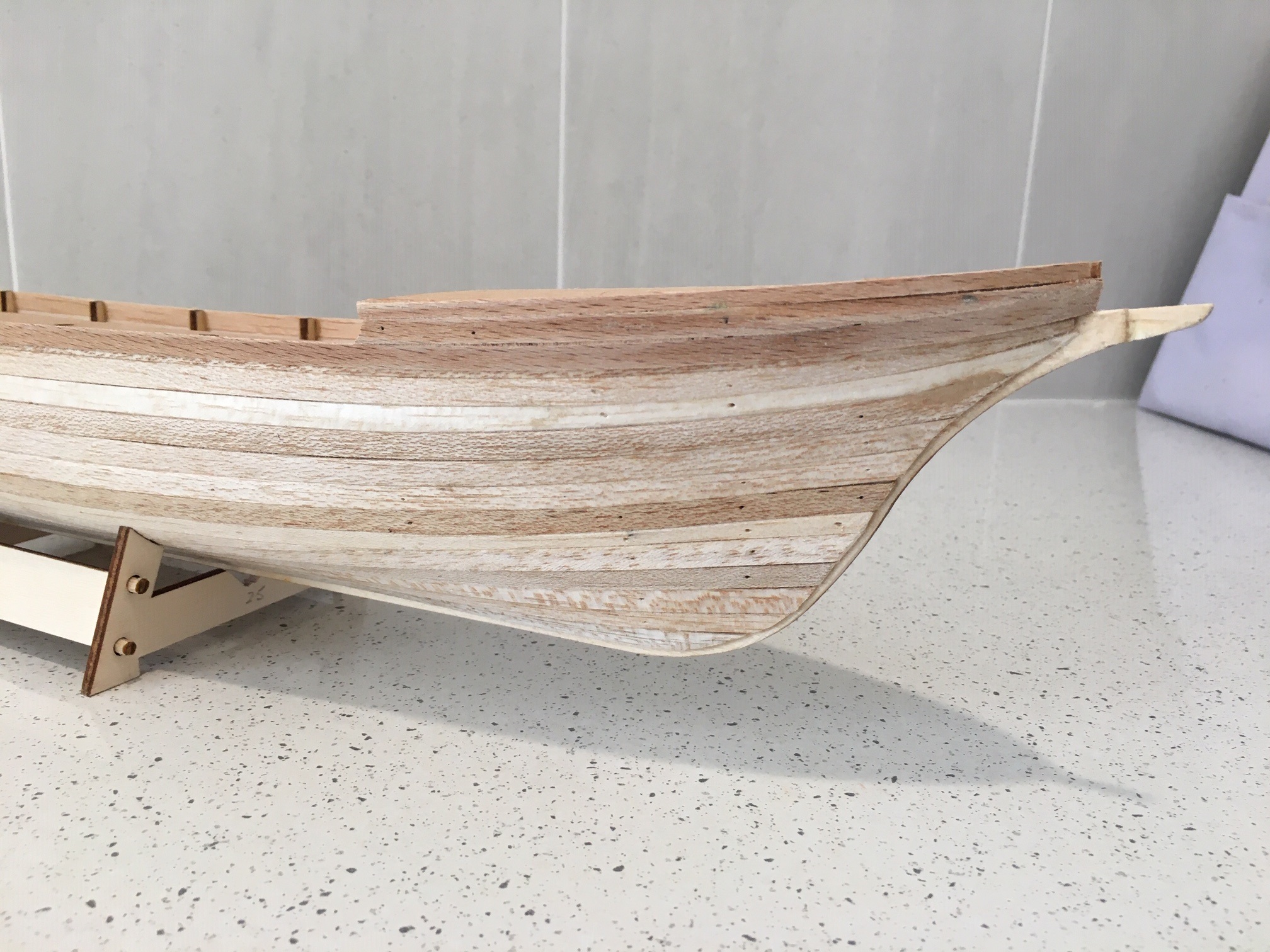
Stern view of completed 1st planking.
This shows where the 1st plank of the 2nd planking terminates. Thereafter vertical planking will be applied around the stern to a similar position on the port side.
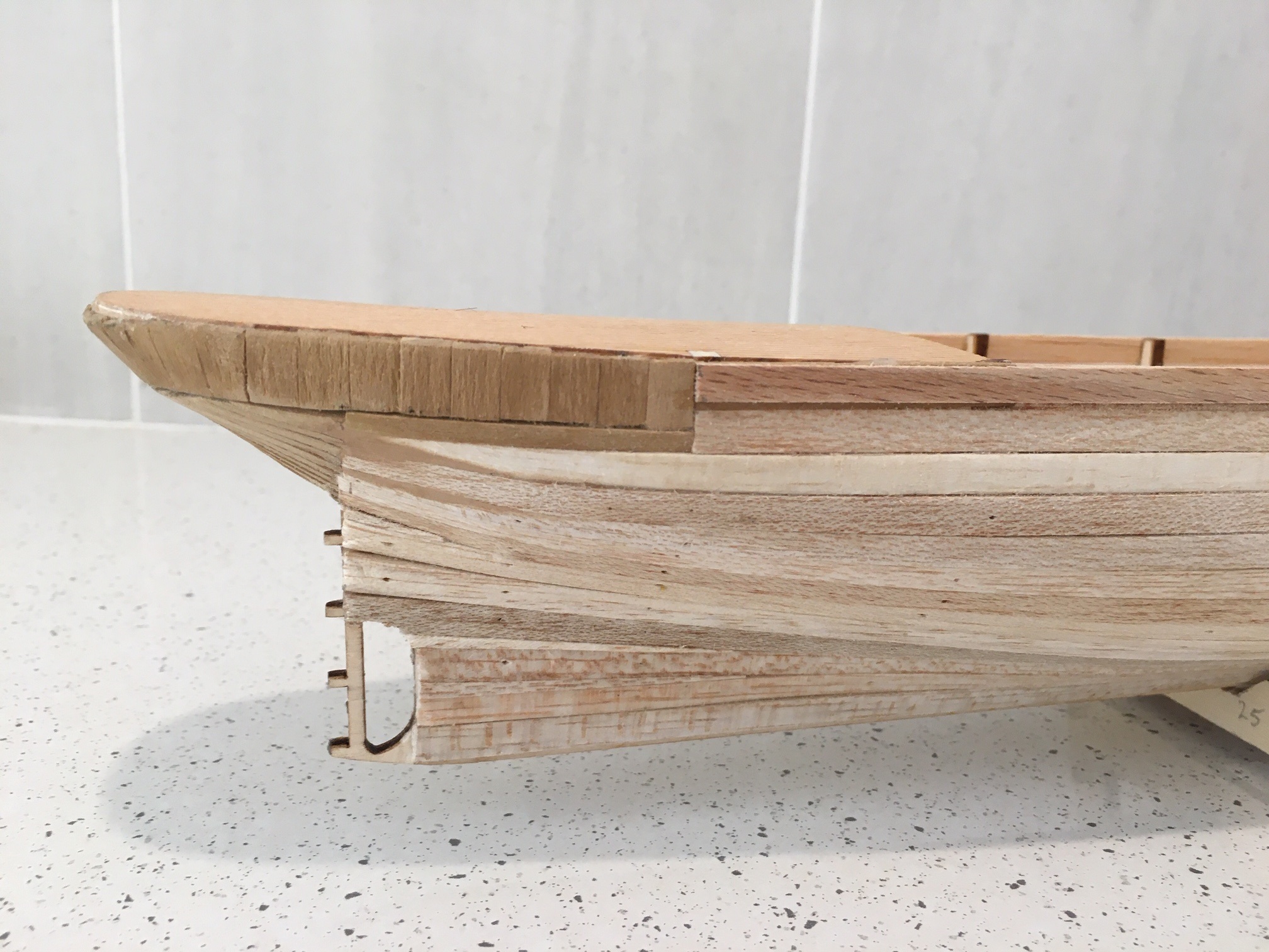
Bow section after 1st planking completed
Here is the bow section showing the addional walnut planking above the 1st of the 2nd planking. Later the jointing of the planking with the keel will be tidied up. As the bow topside will be 'holed' to accommodate the bowsprit, the top ends have not been glued together.
Second planking completed

The second planking, using 4 x 1 mms tanganyika, was completed on 15/2/2020. The current kit model being used in this case, did not call for a second planking - which was considered rather strange as the original model of Mercator made in 2008 did so and had turned out to be an excellent display model.
Fortunately, sufficient tanganyika timber saved over the years was available to cover the hull with a few lengths to spare! After appropriate sanding to achieve a satisfactory smooth finish, Caberthane clear water based sealant was applied to protect the hull from accidental 'bruising'!
Deck planking completed
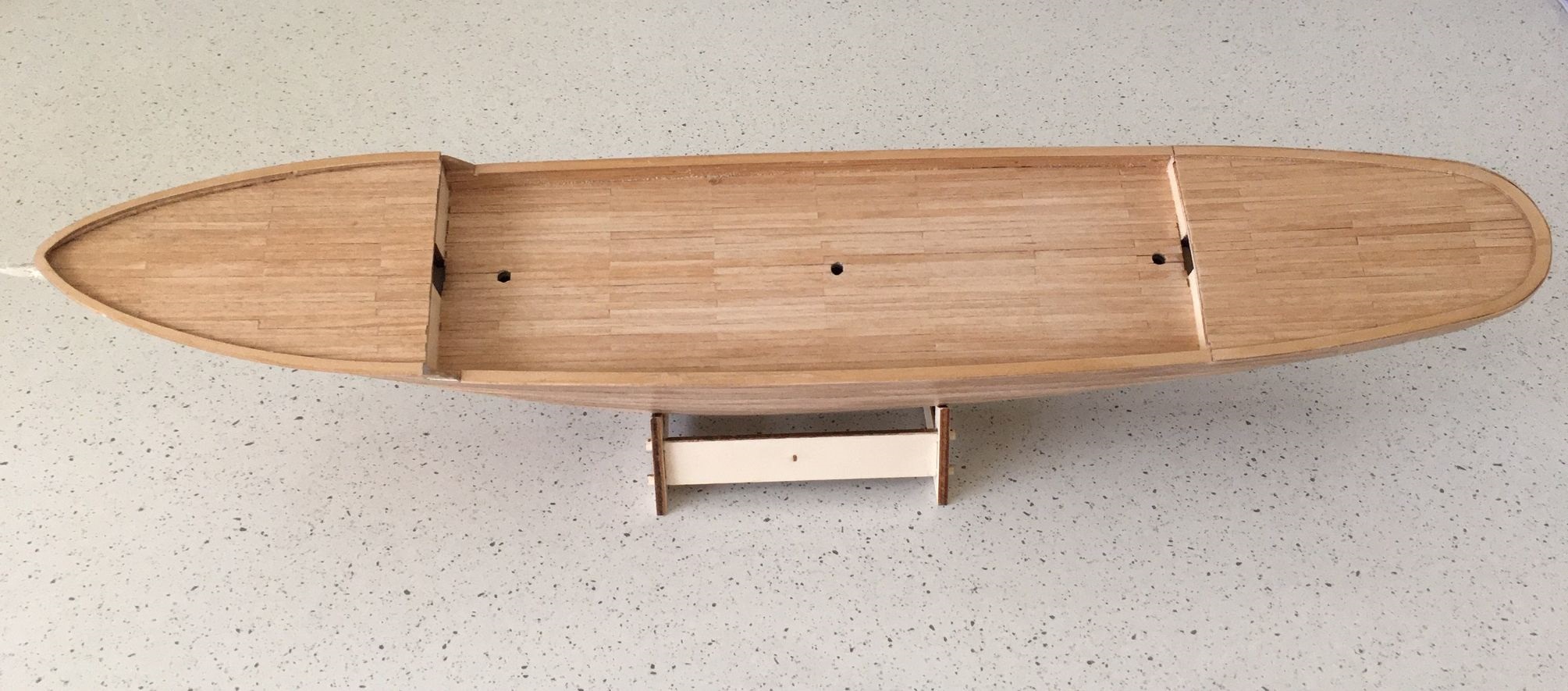
The original decking on Mercator 1 was provided stamped on laser cut plywood in a correct layout and therefore was untouched. The decks provided in the current kit were stamped but with only fore and aft lines each 1 mm apart. Thus it called for an overlay to make the model authentic. To undertake this task, 15 x1 metre lengths of tanganyika timber were bought and laying commenced on 16.2.20 and completed on 21.2.20. The deck was then sanded and sealed as per the hull.
Hull painted in authentic livery

The hull being ready for painting, the cutline for the waterline was determined and highlighted underneath it with good quality masking tape on both sides. Three coats of water based white matt finish acrylic paint was applied - each coat being left overnight to ensure total drying. Two coats of water based clear Caberthane acrylic was then applied, creating a fine gloss finish.
The masking tape was removed with ease when the above was firmly dried, leaving a very clear cutline. Fresh masking tape was then applied above the cut, on the painted white sector, on both sides. Three coats of carbon black water based acrylic paint was then applied over a three day period. As with the white, two coats of clear acrylic were then applied. To complete the exercise, when completely dry, the masking tape was removed with no adverse effect on the white paint.
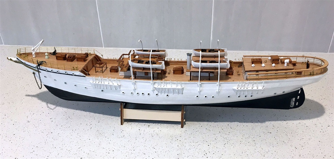
Starboard side shown
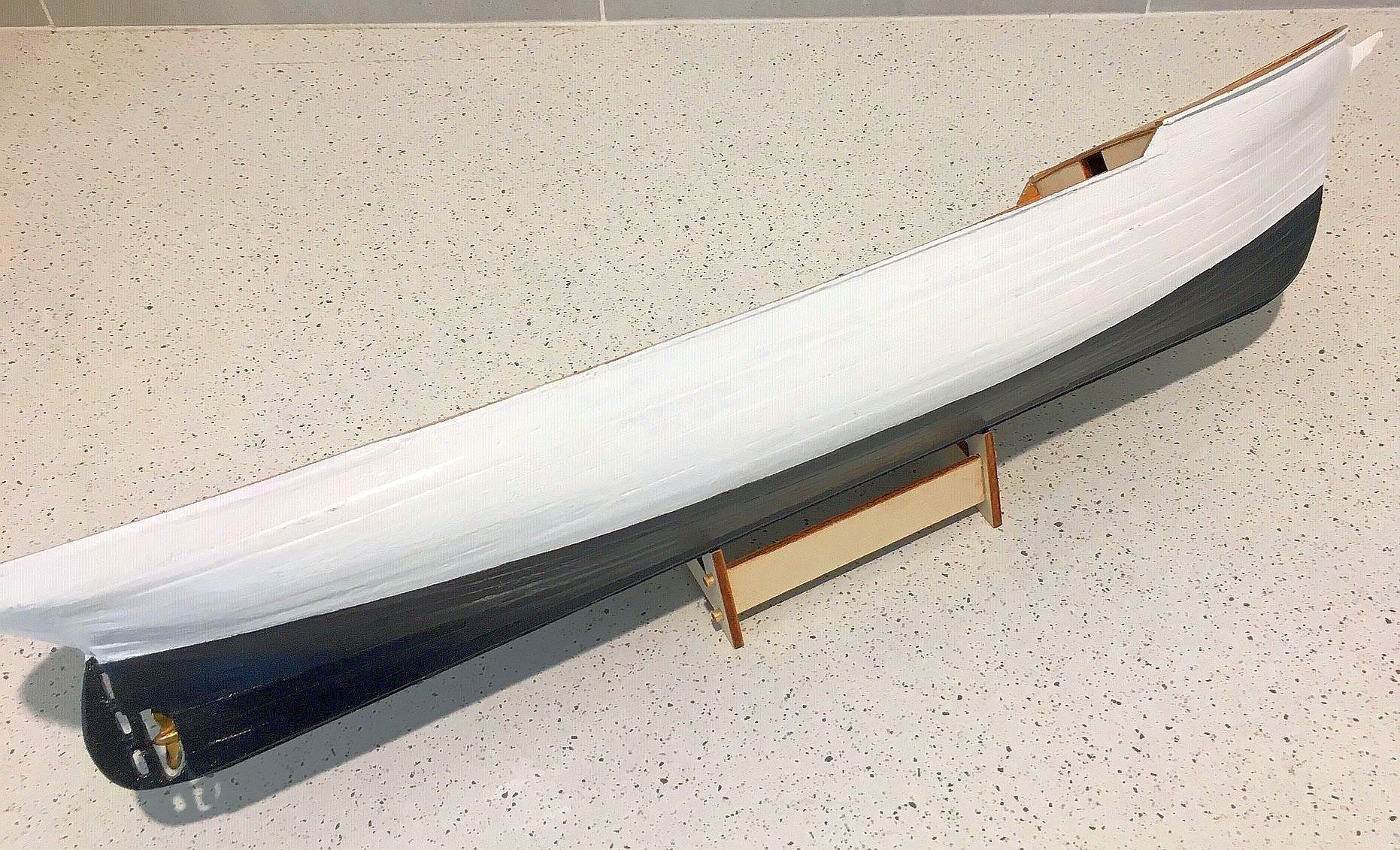
This aspect of the painted hull shows the waterline a little more clearly, with the model displayed lying on its side.
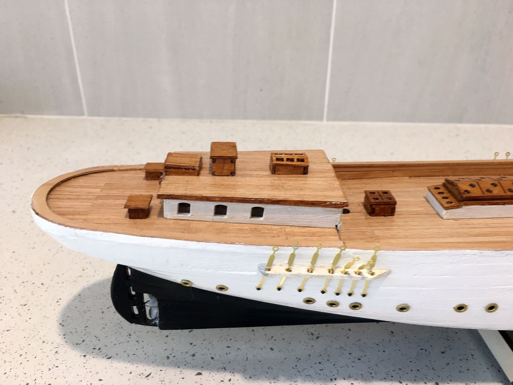
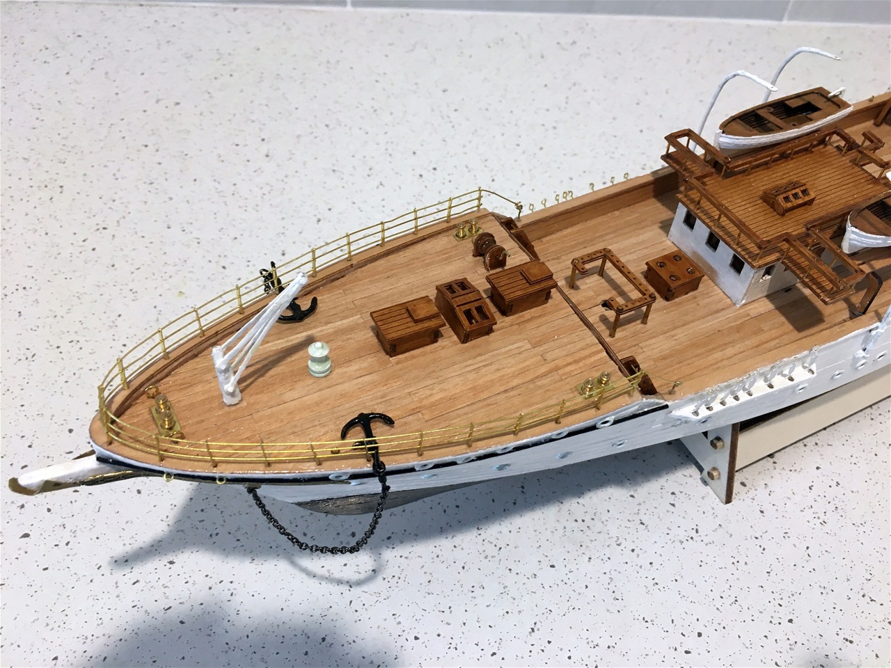
Side fittings and some deck fittings in place
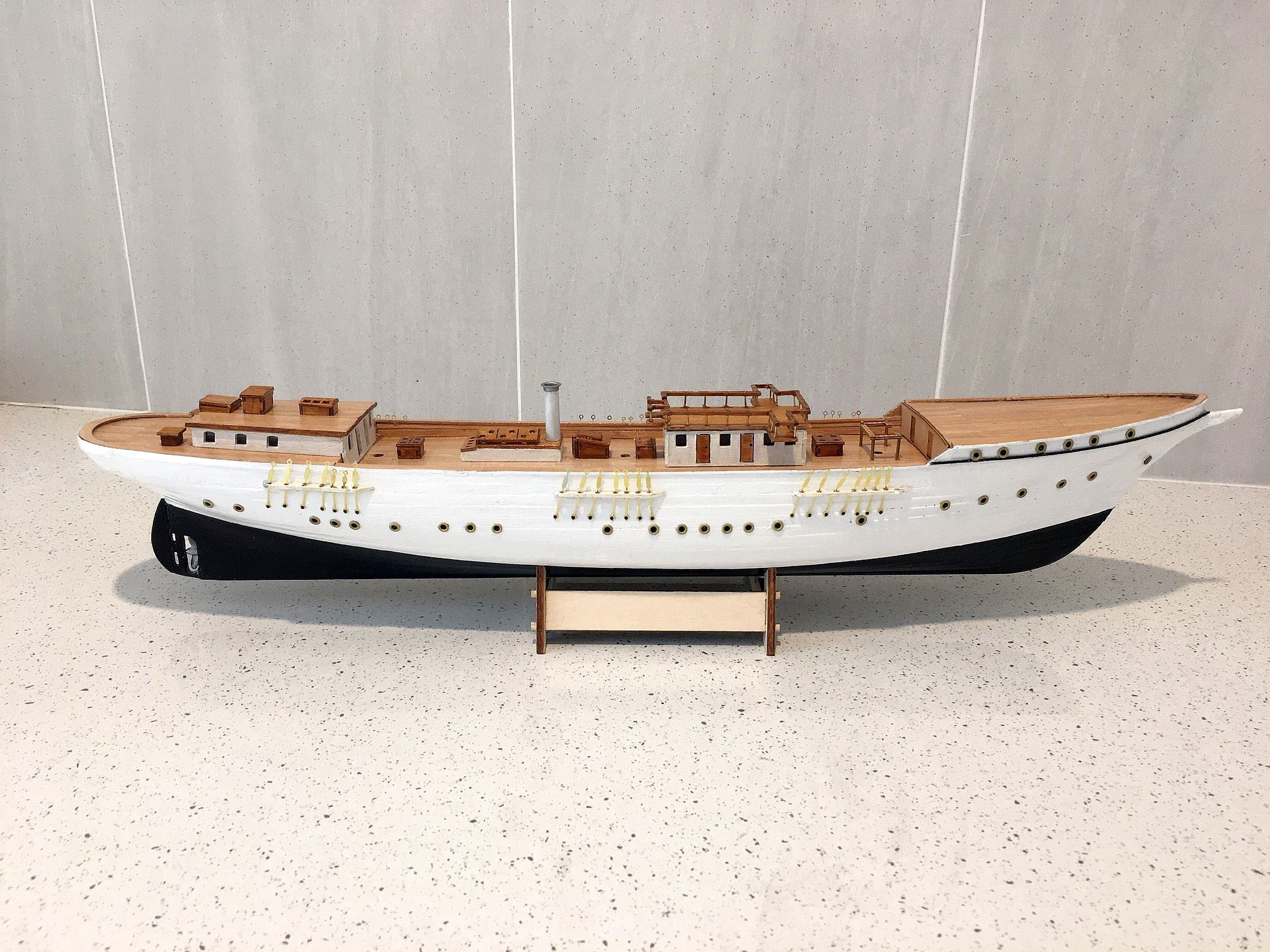
With all the external painting completed the channels were attached, after the pre drilled deadeye holes were enlarged to accommodate the chain plates. These were then fitted with the chainplates with extreme care as they are made of fine flat brass plate and are prone to break easily.
As the decision to insert portholes was made - which were not supplied in the kit, although a diagram indicating the correct positioning was printed in the booklet - it was prudent to do this prior to attacking the deck work. Altogether 56 ports were inserted as near as possible to the correct positions.
There were some discrepancies in the measurements between the booklet and the actual spaces on the model. The end result was very close to the actual real life photographs of the vessel in Ostend moorings.
The bridge deck and engine room
When assembling the bridge deck from the laser cut sections supplied, it was found the hand rails, supplied in a single cut out of 2 x 1 mm timber, did not take kindly to the 1mm drilling required in which to set the brass posts. Hence it was replaced with 2 x.2 mm hardier timber from our stock. This created a much longer process as, at all the corners, the straight sections had to be cut to size - the smaller ones being as little as 1.5 cms with two posts. After about four days of patient attempts, the final result was acceptable.
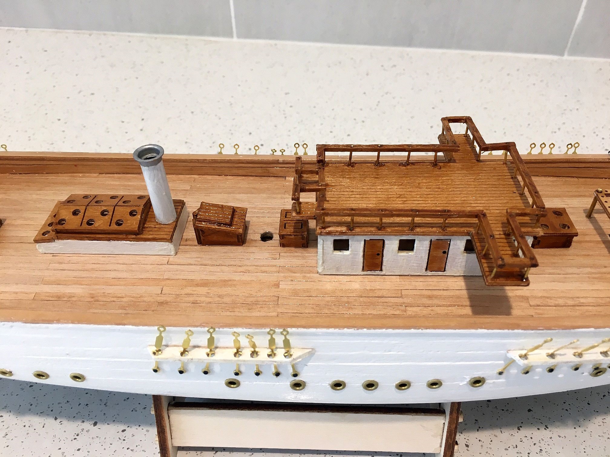
The poop deck fittings
The poop deck housing in the model shows the 3 windows at the forward end of the housing whereas the actual vessel has windows all along the housing. A decision was made to place them at the after end, for asthetic reasons, and a fourth window was added on both sides equidistant from the forrard window shown in the attached photo. The additional windows will be seen on the next photo taken.
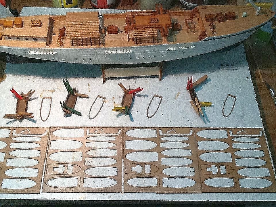
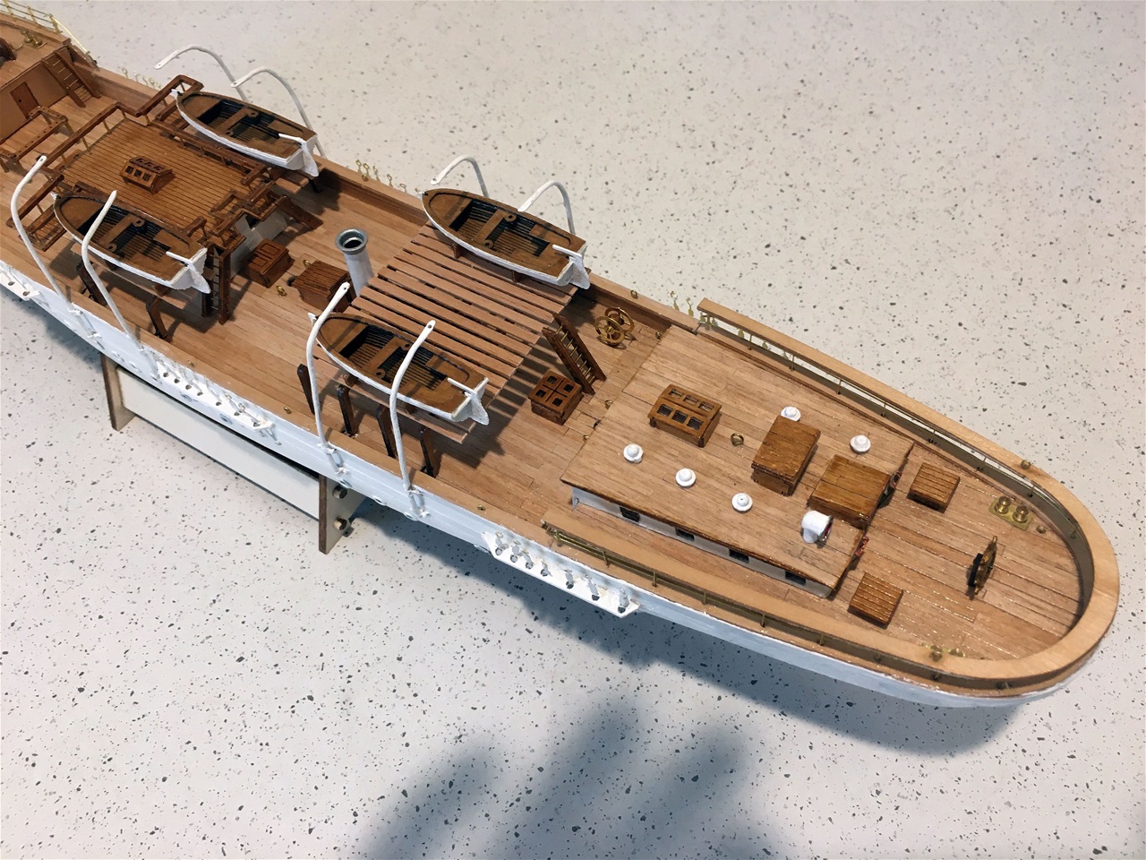
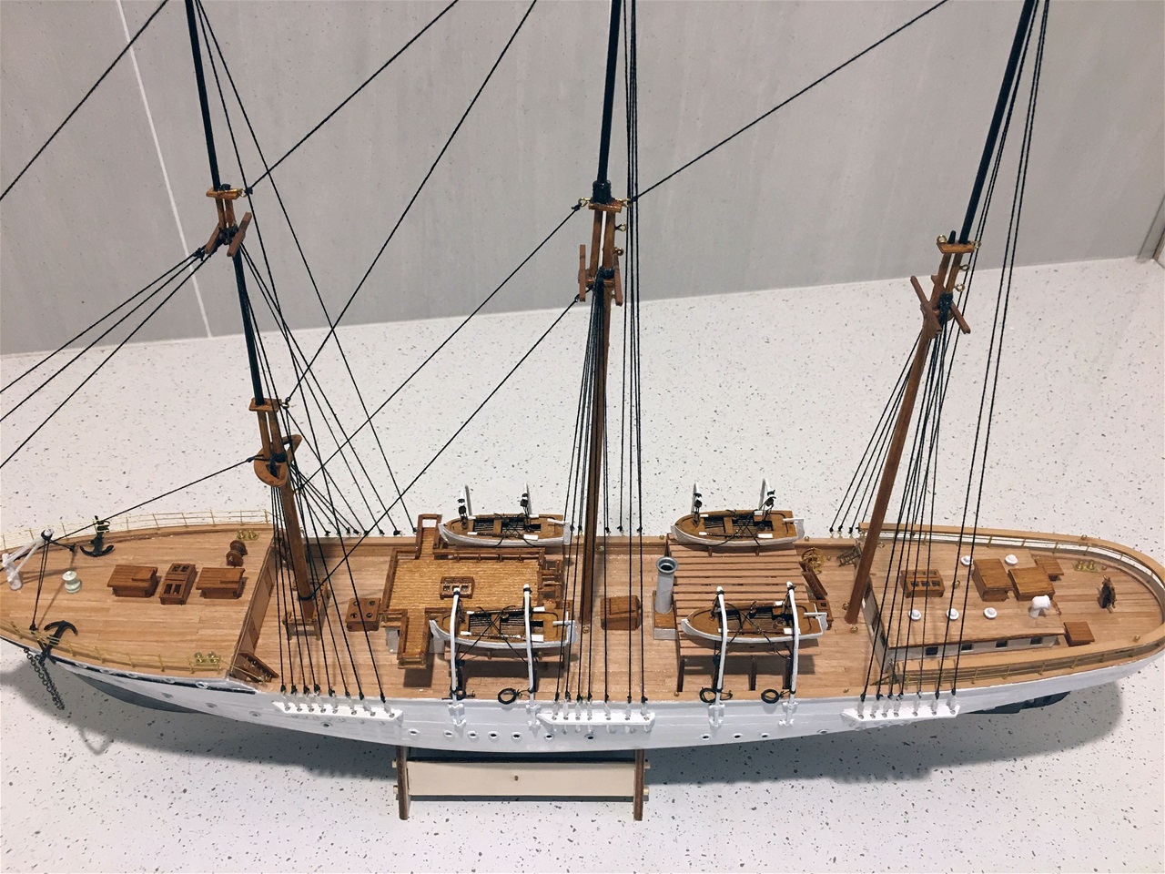
Deck houses in place, lifeboats underway
Due to the Corona virus, we in Australia are virtually under complete lockdown. This means, amongst many other severe restrictions, us senior citizens are confined to 'barracks' and should only leave home for really essential reasons, such as to GP"s etc. We are fortunate enough to have younger neighbours who are keeping us well supplied with the necessities supplimented by visit from Sydney based family.
Many residents are finding this isolation difficult to come to terms with but, in our case, it is no problem and is giving us more time for our hobbies! Consequently, more progress has been made on Mercator over the past three weeks, as can be seen from the photo attached. There have been a number of hiccups on the way which are explained in the next section but one. Most of the major items on deck are now in place with the two housing decks for the lifeboats being the latest addition.
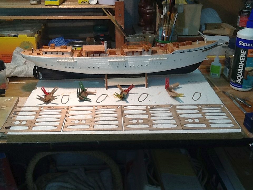
Lifeboat construction

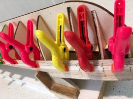
The lifeboats are constructed in a manner to represent the clinker style by glueing 13 individual laser cut sections in a particular order. It was decided to lay out all of the cut outs alongside each other and one by one, glue each part. By the time the fourth had been glued, the first was sufficiently dry to allow the attaching of the next. The photo shows all the parts removed except for the last two, with a third last awaiting placement.
The only point to raise about this excercise is that the instructions say to use instant glue whereas aqauadhere or similar is quite satisfactory. Instant gives insufficient leeway to interlock the very small parts correctly. (Slow and steady wins the race!!). The use of small and/or medium size clothes pegs to hold the sections in place, works well.
Overview of construction
Reverting to the hiccups, for the inexperienced builder, the instruction booklet leaves a lot to be desired. The numbering of the illustrations and pics on pages 10, 11 and 12 are complex - some being circled and others not, with many duplications of numbers. Very limited instructions are available with most comments saying 'follow the drawings' - which are also lacking in detail.
Deck fittings complete
A number of the remaining deck fittings, such as the davits, the foredeck and after deck hand railings took time and patience to get them fault free. The posts for the railings are flat brass cut-outs complete with three 0.5 mms drilled in them. 0.5 holes had to be drilled in the bulwarks to accommodate them at carefully measured distances. Then 0.5 mm brass wire (generally in coils) had to be stretched as straight as possible then, estimated total lengths of the perimeter cut and carefully thread throughout. The ends were then instant glued at the final posts each end.
Foredeck complete
This features the foredeck railings in particular, showing the equidistant posts and the final securing to eyebolts on the well deck.
After decks complete
Here are shown the poop deck railings which have just two lengths of 0.5 mm wires with a timber rail instant glued to the top of each of the posts (with very little contact on each post being also 0.5 mm at the top). Also seen here are the davits made from 1.5 mm round brass rod which also had to firmly stretched prior to cutting to 8 x 80mms lengths. These then had to be shaped top and bottom at correct angles to overhang the lifeboats amidships.
Below is a diagram indicating the methodology employed.
Diagram of Davit construction
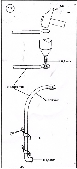
The diagram shows the requirements for making the davits suitable for this vessel. Obviously the dimensions will vary according to the vessel in question.
Note there is a need to hammer the top end forming an eye sufficiently wide enough to take a 0.8/or 1.0 mm drill bit. Not easy unless the right tools are available!
Also note at the base, the right angled bend to be inserted into the hull does not include a measure as to how much needs to be inserted. In this case, about 5-7 mms is sufficient.
The problem here is that the brackets supplied in the kit were a 'tad' too small with the semi-circle section smaller than the 'round' of the davit. It was either the case of obtaining/or making larger or 'making do' which was done in this case but with some trepidation!, but success.
Rigging underway
Having now completed all the necessary deck work, concentration turned to the fashioning of the masts, yards and booms. The widest dowling to be used was just 5.0 mms for the lower mainmast and the main boom, with the main and mizzen topmasts being 3.0 cms and the fore topmast just 2.0 mms, it was relatively short work to fashion them. The drill and sandpaper method was used for the larger dowling whilst the smaller trimming was done by hand. The Foremast has 3 sections of masting and the Main and Mizzen two. Extreme care was needed and much fine needle filing required on the joining of the sections to ensure tight fittings.
Once complete, the masts were set in place to ensure the correct angles were achieved and the mast were sufficiently 'tight' in the deck apertures. Once satisfied, they were glued in place and the Stays and Shrouds, using black 0.5 DMC cotton.
View from above of masts and standing rigging
This shows the a clear view of the seating of the masts and the fastening of the standing rigging. It should be pointed out that, in accordance with the actual system used on the 'real' vessel, no use is made of the normal use of deadeyes, straps and/or chains for the shrouds but one piece brass straps with a hole top and bottom are used. The bottom to secure them to the hull and the top acts as a securing point direct with the shrouds.
View of poop deck
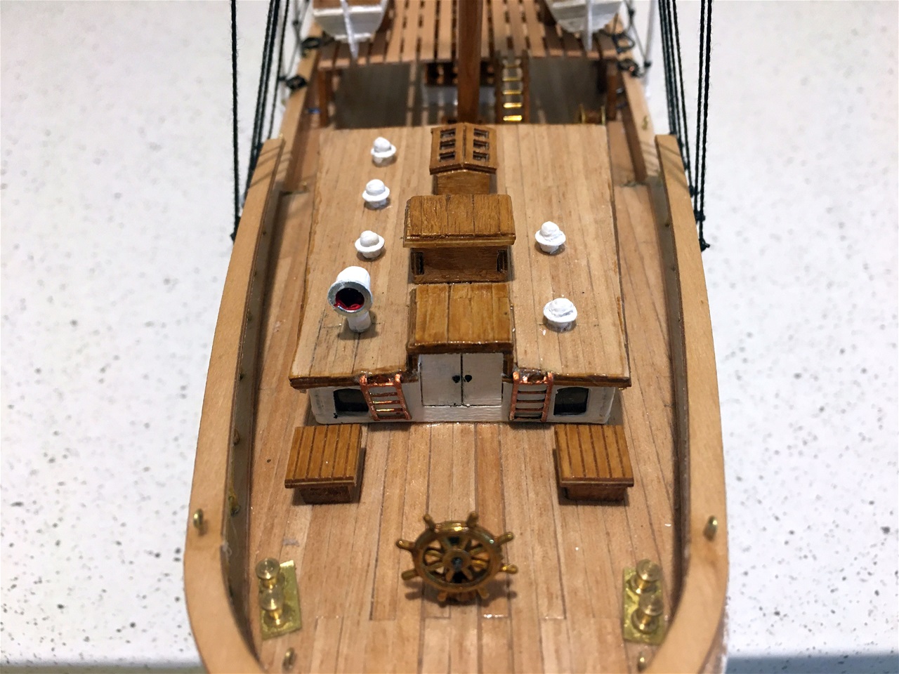
The purpose of ths photo is to emphasise the fact that the poop housing is fitted with ventilators on the model which are not actually in the kit but are on the ship itself. The following photo repeats the scene from a lower aspect.
View from astern

This photograph attempts to emulate the photograph of the real vessel standing in Ostend harbour, showing the placement of vents not actually included in the kit.
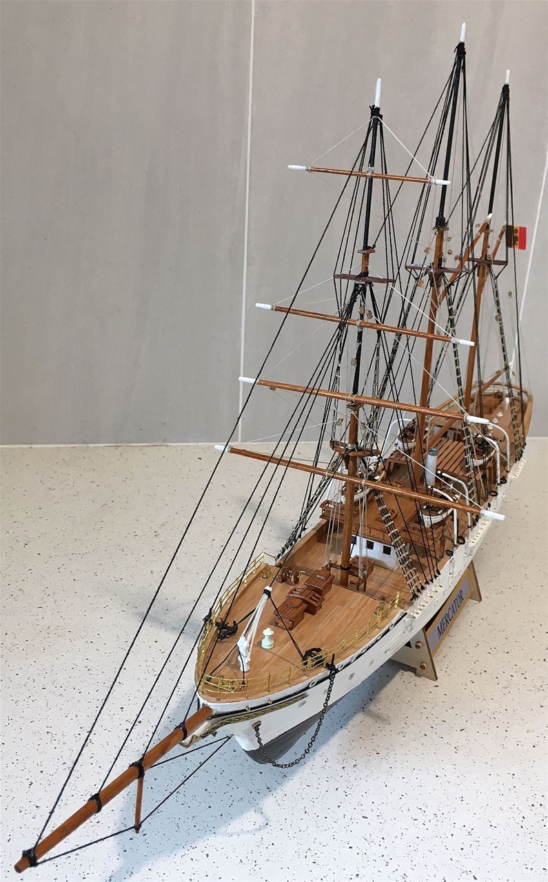
How slender is this vessel!

An unusual aspect from forrard showing what a 'slender' beam this ship has compared with many of its kind.
Three ladies admire the completion
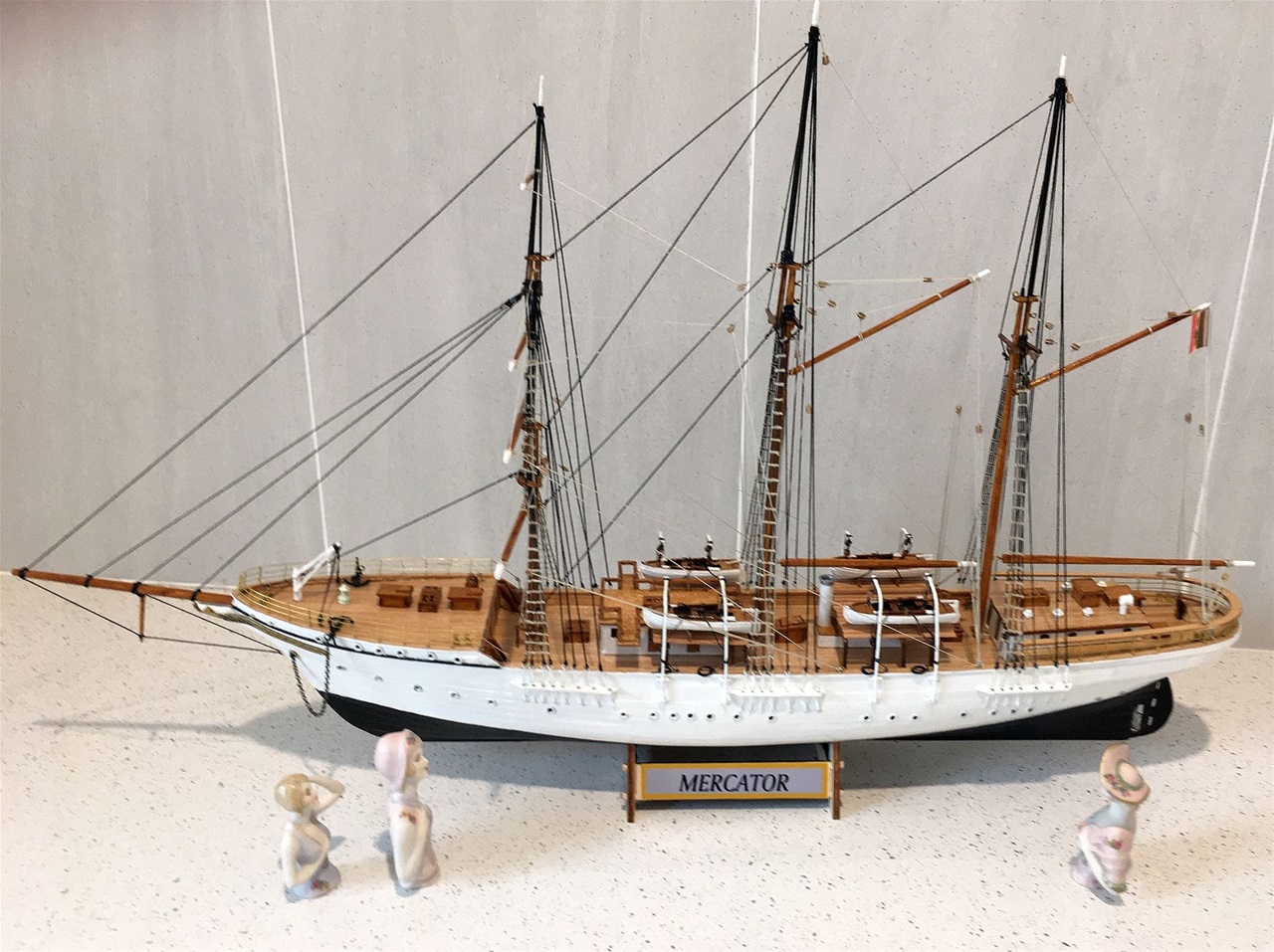
Three of my wifes creation half dolls admire Mercator from the port side. The final touches were completed on Tuesday 21 July 2020 with the nameplate being designed and appplied on both sides of the stand which was then glued to the hull.
Midship section from port side
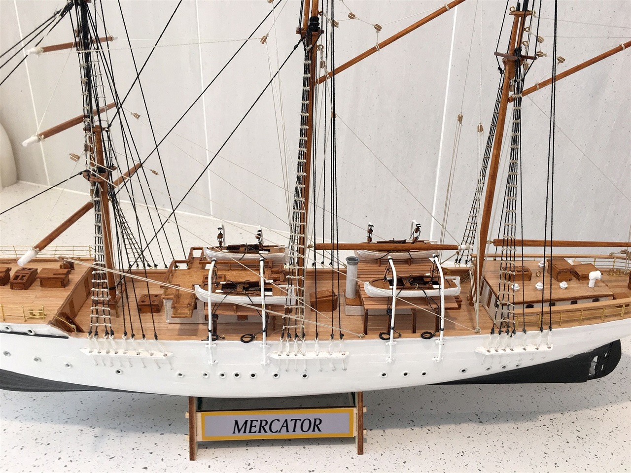
This view of the port side shows the securing of the lower ends of the standing and running rigging. During the rigging procedure, a mstake was 'almost' made when the foremast yards were attached and the running rigging started. It was quickly realised the ratlines should have been completed prior to this action as otherwise rigging would hamper the activity. This was then completed before the running rigging was continued.
The shrouds and other standing rigging was completed using black DMC 12 0.5 mms pure cotton. The running rigging was done with DMC 8 0.26 beige pure cotton. In the photography it is hard to distinguish the cotton sizes as the lighter colour sometimes appears thicker than the black - which is not the case. In the model, the shrouds containing the ratlines are relatively close to each other and thus the ratlines tend to 'bunch' more than is desired.
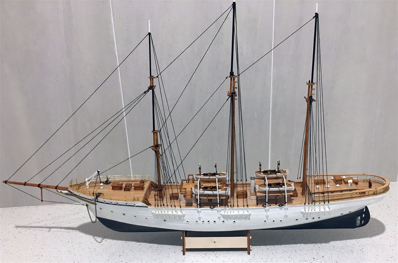
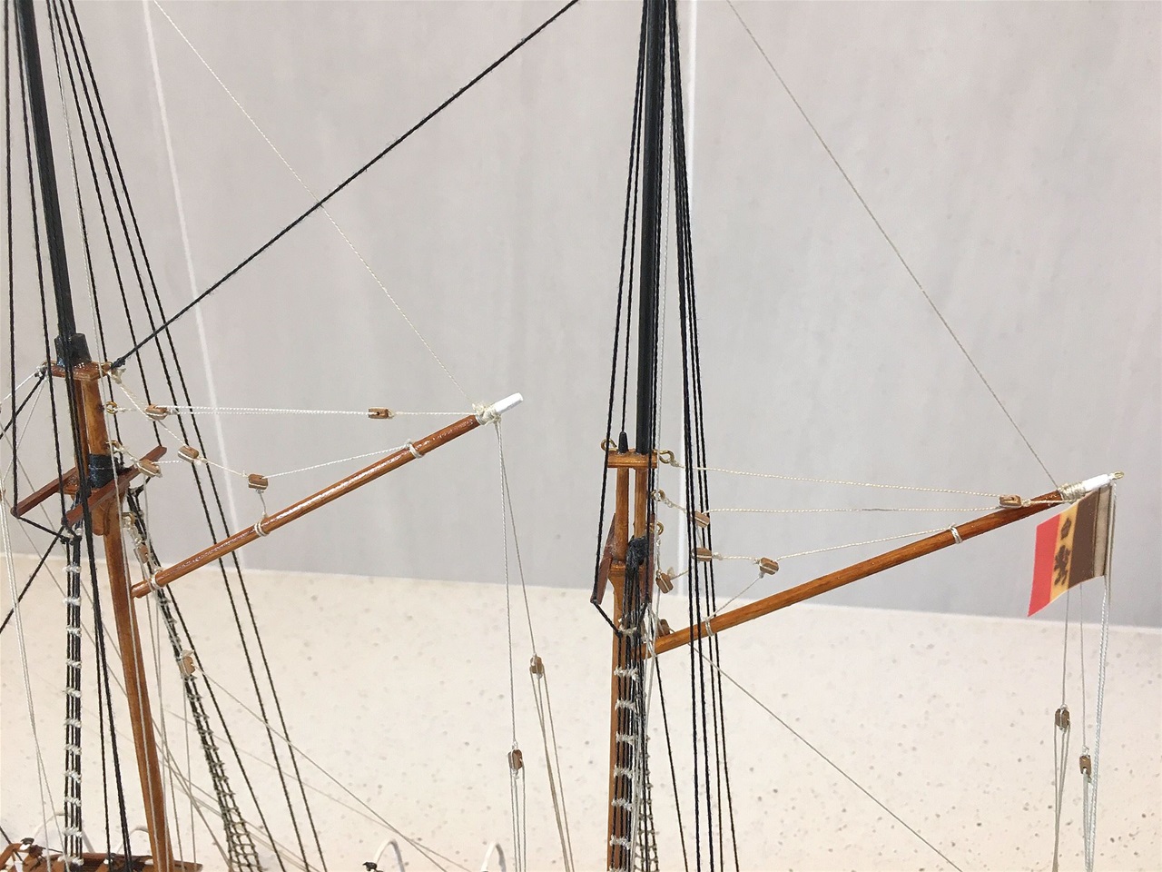
View from ahead on port side
THis portrays the masts and the yards on the foremast for the sqare sails as compared with the main and mizzen which are fitted with booms for the fore and aft sails.
The Main and Mizzen upper boom rigging
The most challenging part of the rigging in this model is the upper boom conglomerate of 3mm blocks which appear to be rathe excessive for the job they perform. During the proceedure, it was found there was a considerable difference in the plan drawings for the securing of some of the running rigging at deck line. When compared with the Mantua large photograph on the cover of the kit box, the later showed direct securing of the lines to the eye bolts while the plan had additional blocks where they were not neceassry. Hence the Mantua photograph system was adopted as it appeared to be the most logical.
So now the base plate has to be made followed by the construction of the perspex cover, both of which are outsourced, and that will bring the Mercator 2 challenge to a conclusion.
Updated 21/7/2020