Classic Ship Model No 28
Rattlesnake American Privateer of 1780

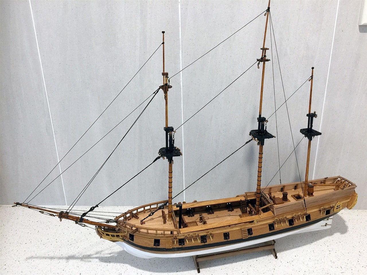
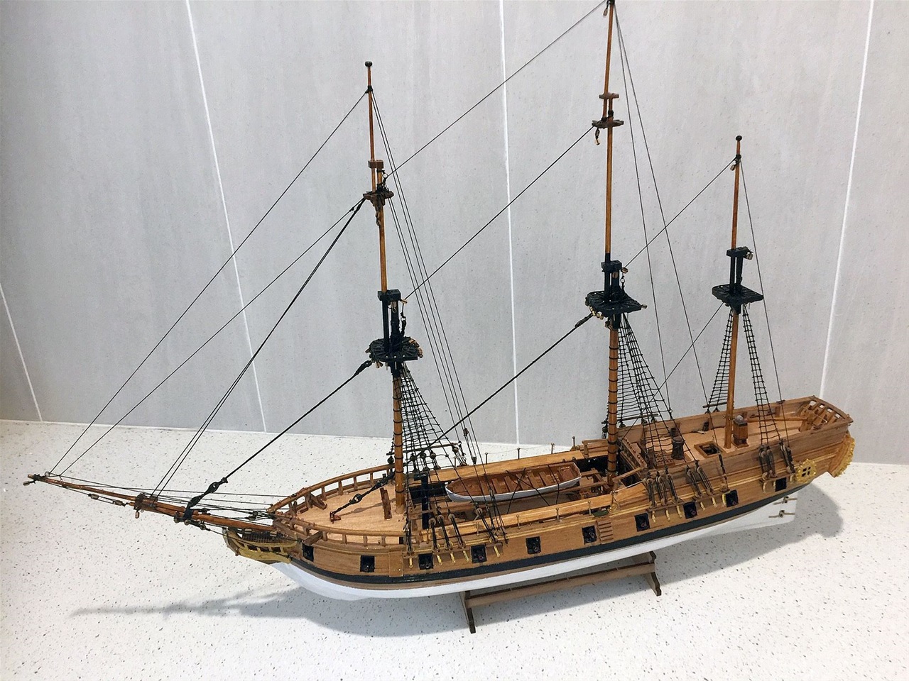
Photograph by Mamoli of completed model
The Rattlesnake was a Privateer built around 1780 in Plymouth, Massachusetts, USA from designs purported to have been produced by a John Peck. Under the ownership of a John Andrews the vessel was initially commanded by a Captain Mark Clark.
She was first commisioned in 1781 but on an early cruise on June 17th was captured off the east coast by the Royal Navy's 44 gun frigate "Assurance", under the command of Captain James Cumming, From there she was sent to New York, arriving on July 8th, and three weeks later purchased by the Royal Navy in Boston.
Taken to England in November '81 with Captain John Melcombe in command, she carried the first news of General Cornwalis's surrender at Yorktown. On November 30th, she was renamed the "Cormarant", as the Navy already a "Rattlesnake" in service. Having undergone re-fitting at Plymouth between November 1781 and February 1782, she entered coastal service recapturing a vessel "Marine" on the 19th July after the Master had put into Torbay to avoid a French privateer.
On July 30th, Cormorant intercepted and captured the French naval cutter "Temeraire" south west of Cape Clear. She was carrying urgent despatches to the French fleet which were thrown overboard, together with log books etc. by the Master, Le Fer. In 1783 "Cormorant" was again named "Rattlesnake".
Being transferred to the Mediterranean fleet, under Captain Melcombe, on the 10th November, the "Rattlesnake" was escorting a merchant vessel "Countess of Tuscany" to Gibraltar when they were waylaid by an Algerian naval squadron of 9 vessels under the command of an Admiral. He refused to believe they were British navy and ordered them into Algiers where they were detained for 5 days before releasing them. On 29th November Capt. Melcombe was replaced by Commander Thomas Hamilton.
In July 1786, the "Rattlesnake" was paid off and sold on 10th October. No further information relevant to her history is available. It appeaers to be a mystery as she was recognised as a very fast sloop/light frigate after her refit.
History by Wikipedia
Making the model - progress 1
The Mamoli model includes extensive plans and instructions which, it is advised, should be thoroughly studied before commencement of the building. Thus this was done to great benefit as one needs to familiarise a large amount of cross referencing between each step of the way.
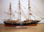
The keel and the frames are firmly set in 4 mms plywood which need a deal of encouragement with a sharp bladed knife to extract. The frames sat well in the grooves of the keel but the main deck 2mm plywood, which was required to be 'bent' to fit into the frames, was another story. The grooves in the decking needed work as there are two raised decks, one forrard and one aft, which have raised 'platforms' on the frames,to be by-passed by the main deck using the 'bending' method. A lot of care and patience required in this exercise! (See frames 1,2 and 3 plus 8,9 and 10 in above photo).
Keel plates in position and glued
The fitting of the keel plates in three sections each side is the last job before the deck planking. Care to double check the fore and aft alignment is important as warping can occur.
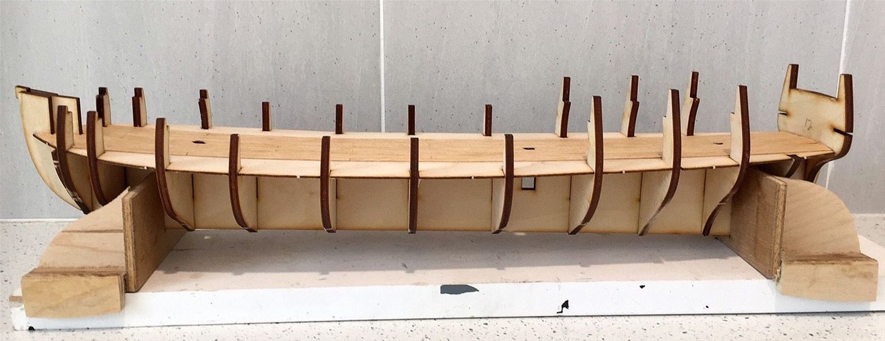
The decking underway
The decking timber used is 0.5 x 4 mms tanganyika with the lengths cut to 80 mm pieces and laid in brick like fashion, which is the normal. The decking laid easily and will extend to the inner side of the frames from forrard to aft. On completion, the foredeck and the poop ply decks are laid and then covered with the same decking.
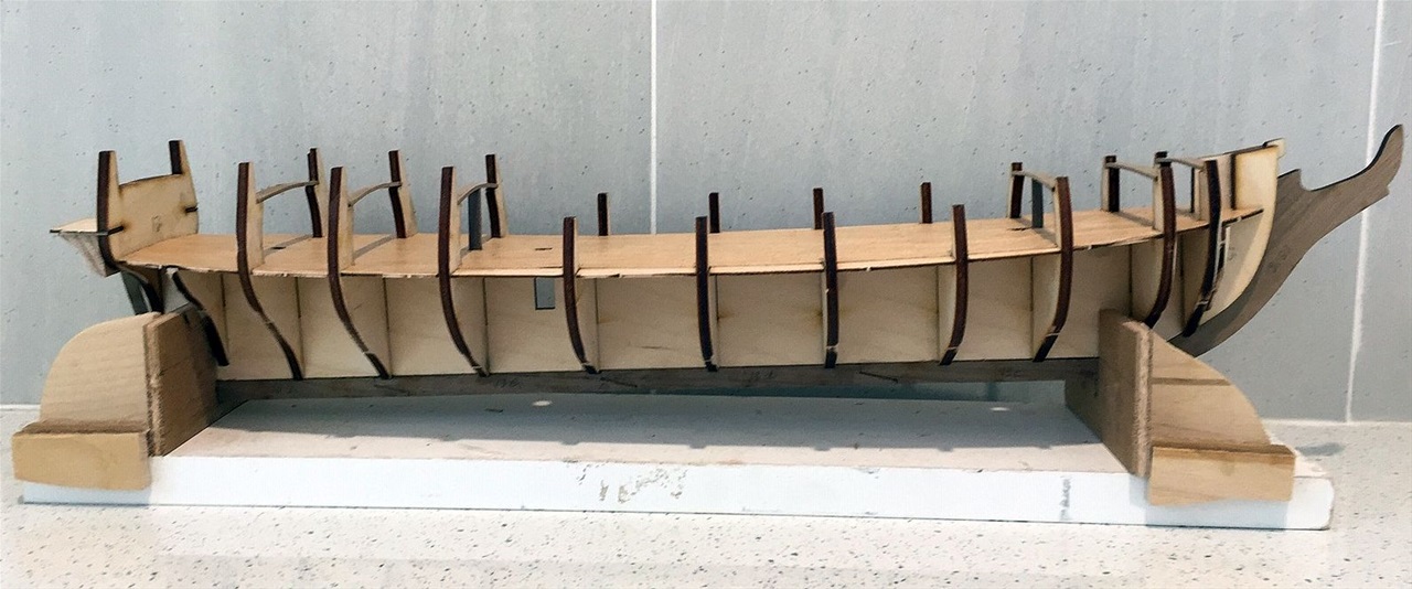
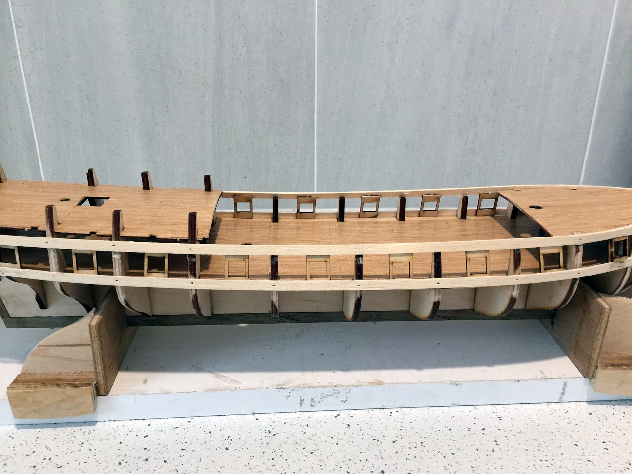
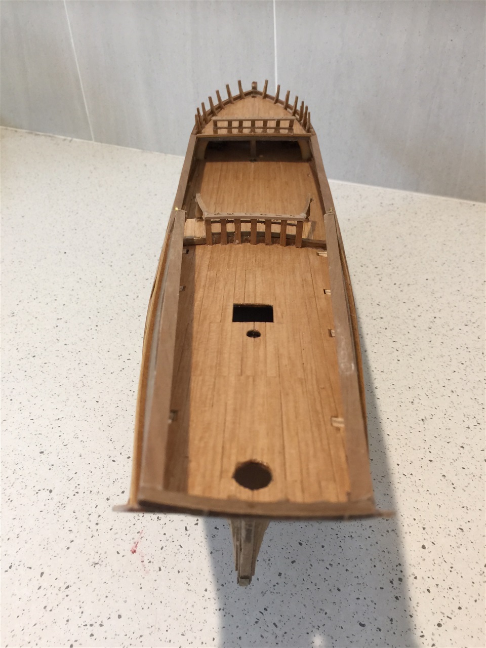
Progress 1, aligning the frames
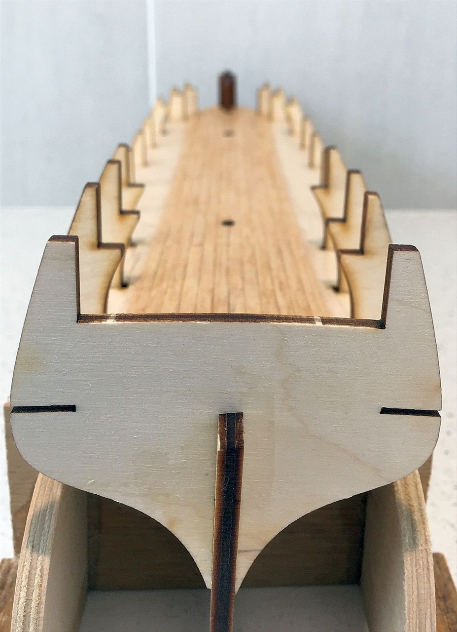
Here the alignment of the frames are seen from the stern, said to be the most important task in the whole construction. Any out of alignment causes a twisting on the keel and thus a tilting of the deck etc, etc. The previous photo shows the stand used in this case, which is found to be useful for this excercise as it does hold the keel firmlly in place and allows the frames to sit correctly. The final 'move' is ensuring the main deck also sits firmly on the frames and are well glued in position and left for 24 hrs to dry hard. The kit maker recommends pinning the decking at an angle to each of the frames at the pont where they sit on each side. In this case, clamps were used with total success.
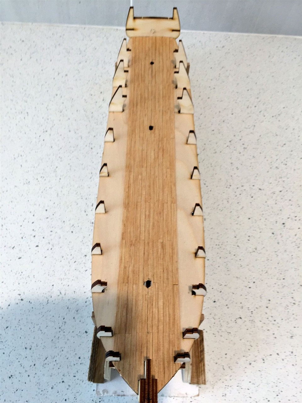
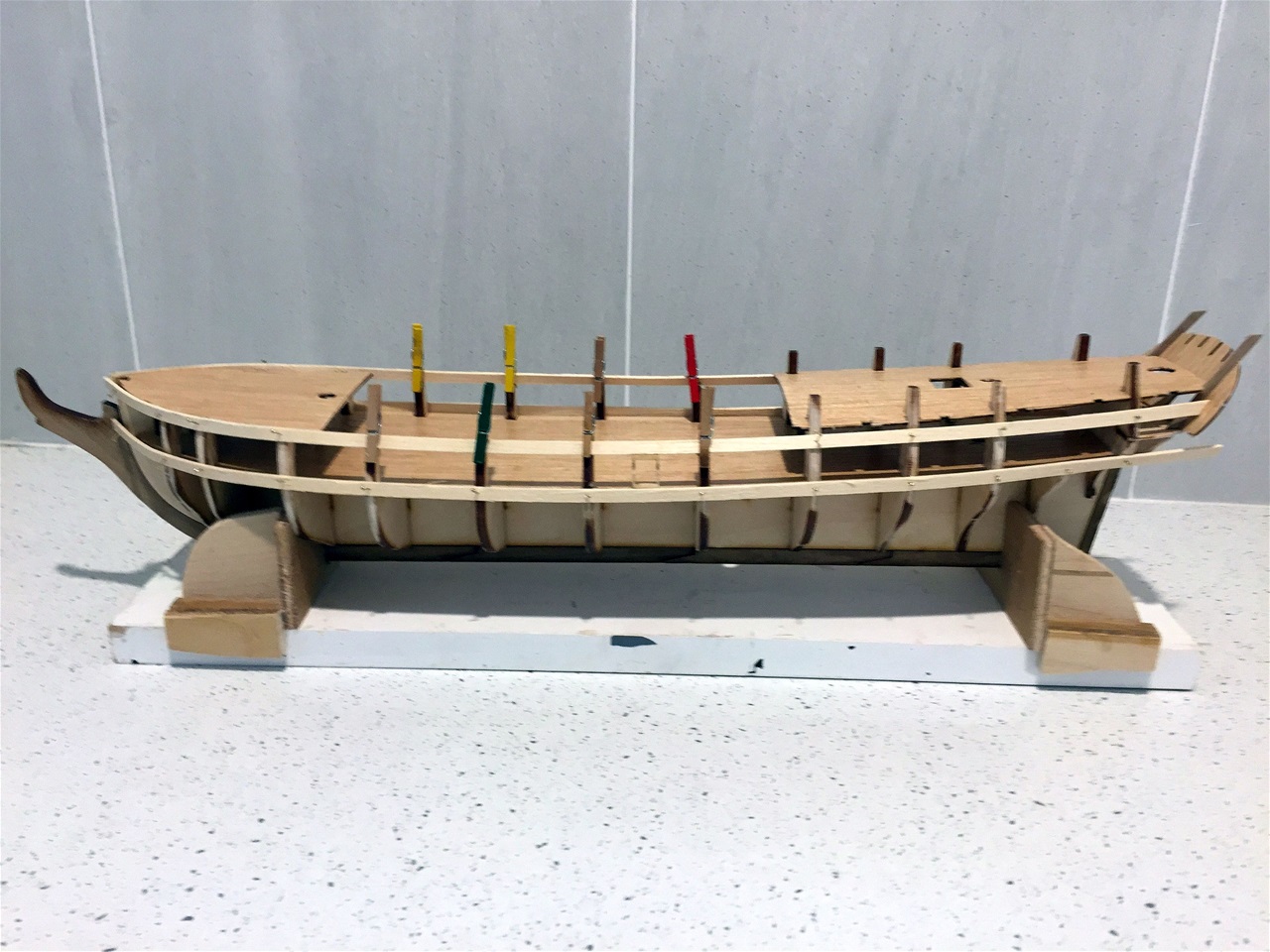
Main deck planking complete

The main deck planking was straight forward and ceased where it reached the inner wall of the frames. There after the two dross beams of 3.0 x 1.0 mms walnut were laid acoss frames 3 and 8 using a template provided for each beam allowing for the curvature of the foredeck and poop deck. After gluing and drying, the templates were removed. These had been held in place using elastic bands firmly wrapped around the beams, after they had been steam ironed to produce the curvature.
Foredeck beams in place

A closer view of the foredeck beams.
A closer look at the poop deck beams in place
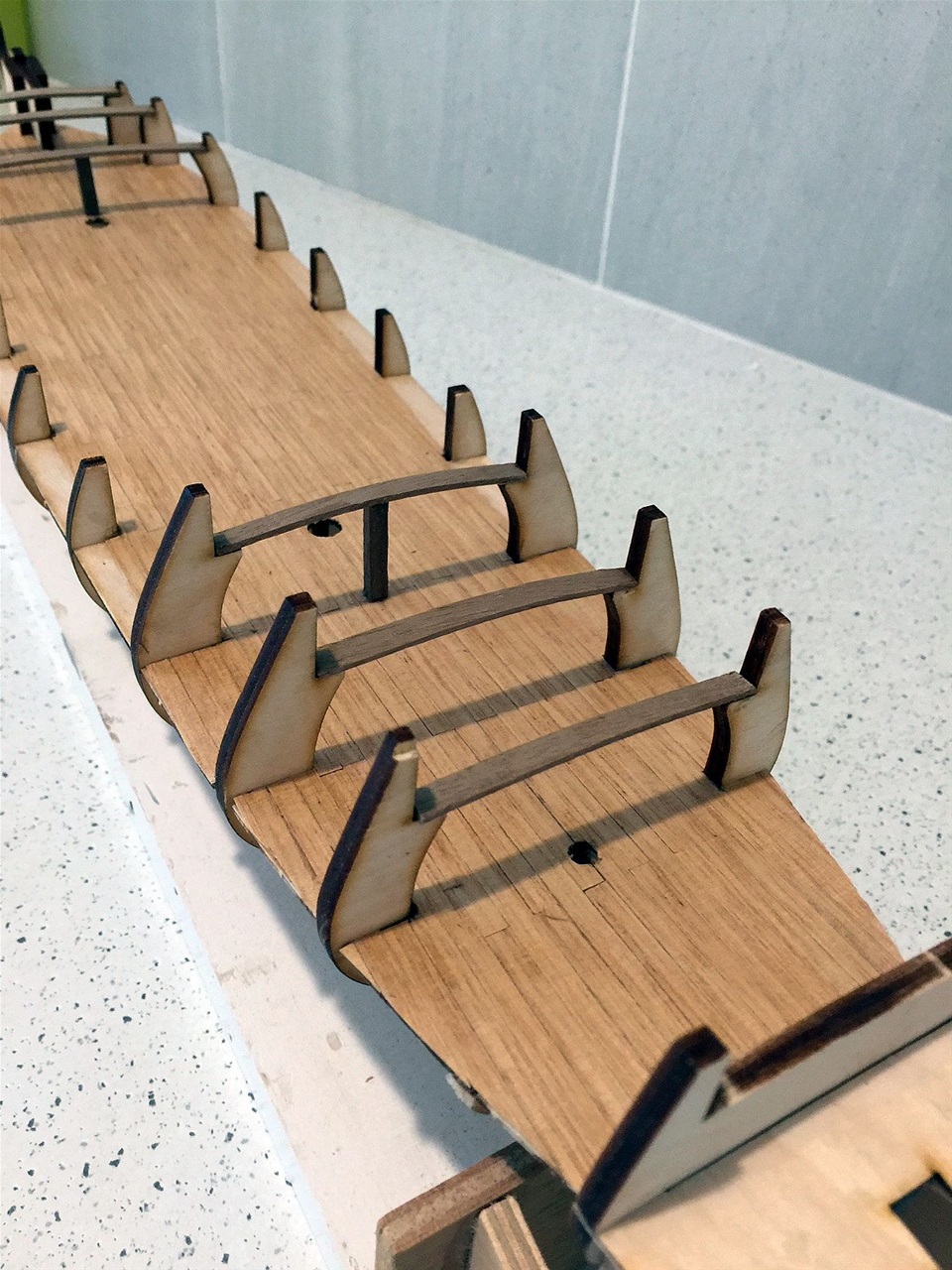
These beams have to be carefully placed with the support post such that a slight camber is made when the upper deck is laid.
The stern strengtheners added
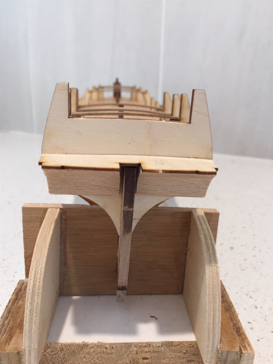
The stern strengtheners had been added prior to the fitting of the beams and support posts.
First two plankings in place
The exact placing of the first two plankings, consisting of 1.5 x 5.0 mms soft wood, is critical in the whole exercise of the outer planking. The first plank must be secured with its lower edge absolutely in line with the lower level of the main deck from forrard to aft.
When the second plank is laid, it has to be at a distance exactly the height of the square section of the gunport doors (referred to as the "portholes in the instructions!"). These ten gunports on each side are supplied in two sections. One is fitted fron inside the planking and the smaller second half from the outside, so the positioning is vital.
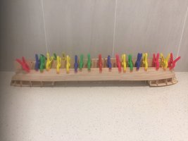
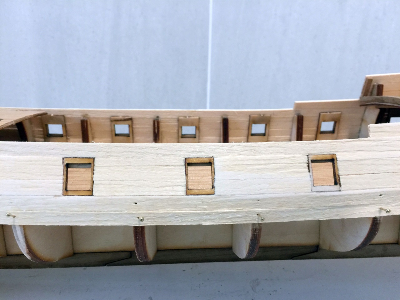
Achieving the exact measurements between plankings

The photograph shows how the outer half of the gunport is used as a template to achieve the precise distancing betwwen the plankings. These are held as a temporay measure between each frame space as the upper planking is pinned in place. This procedure is followed for the entire length between each frame space.
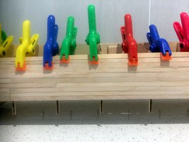
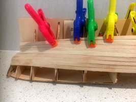
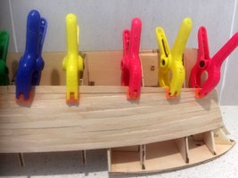
When concluded, the plank is removed whilst glue is placed on the frames before the plank is refitted and re-pinned in place against frames 1 - 3 and 8 - 12 with the intermediate frames secured with mini clothes pegs. This pegging ensures the frames are not damaged by pinning at the 'fragile' top end which can easily be split with a wayward pin!
All gunports in place
All the gunports are completed with the outer frames being fitted over the inner. A number of trimmings were necessary to make them fit exactly and the whole process was quite laborious!
The earlier instructions were to fit the upper deckings in place but this was repeated at this juncture - "after the cannon carriers had been constructed (without the cannon fitted)and placed inside the gunports". Common sense should have picked this up at the time but it was not a difficult hurdle to overcome as they were pl;aced easily by the use of tweezers and a little manipulation after coating the deck with aquadhere, where they were to be secured - four under the foredeck and six under the poop.
The worst challenge was actually preparing the 10 carriers involved - each item consisting of 12 minute seperate wooden sections, each requiring time for the glue to dry before attaching the next!!
Planking around gunports complete
Apart from the need to carefully cut many short sections of the 1st planking to size between each gunport, no problems were encountered.
Close up of gunport surrounds
The close up shows the commencement of the hull first application of planking. Note that pins were used to secure these - a practice avoided when the second planking was done.
At this stage, a substantial time lag occurred due to other commitments and, although some progress was made intermittently, no photos were taken until both levels of planking were complete. Following the fitting of the shear strakes and a series of differing width timbers above and below them, the planking followed the usual procedure with 4x1 mms walnut timbers used for the balance of the outer. The model was then sealed with cabothane water based clear after the hull received a good sanding with minor areas filled to obtain a smooth finish.
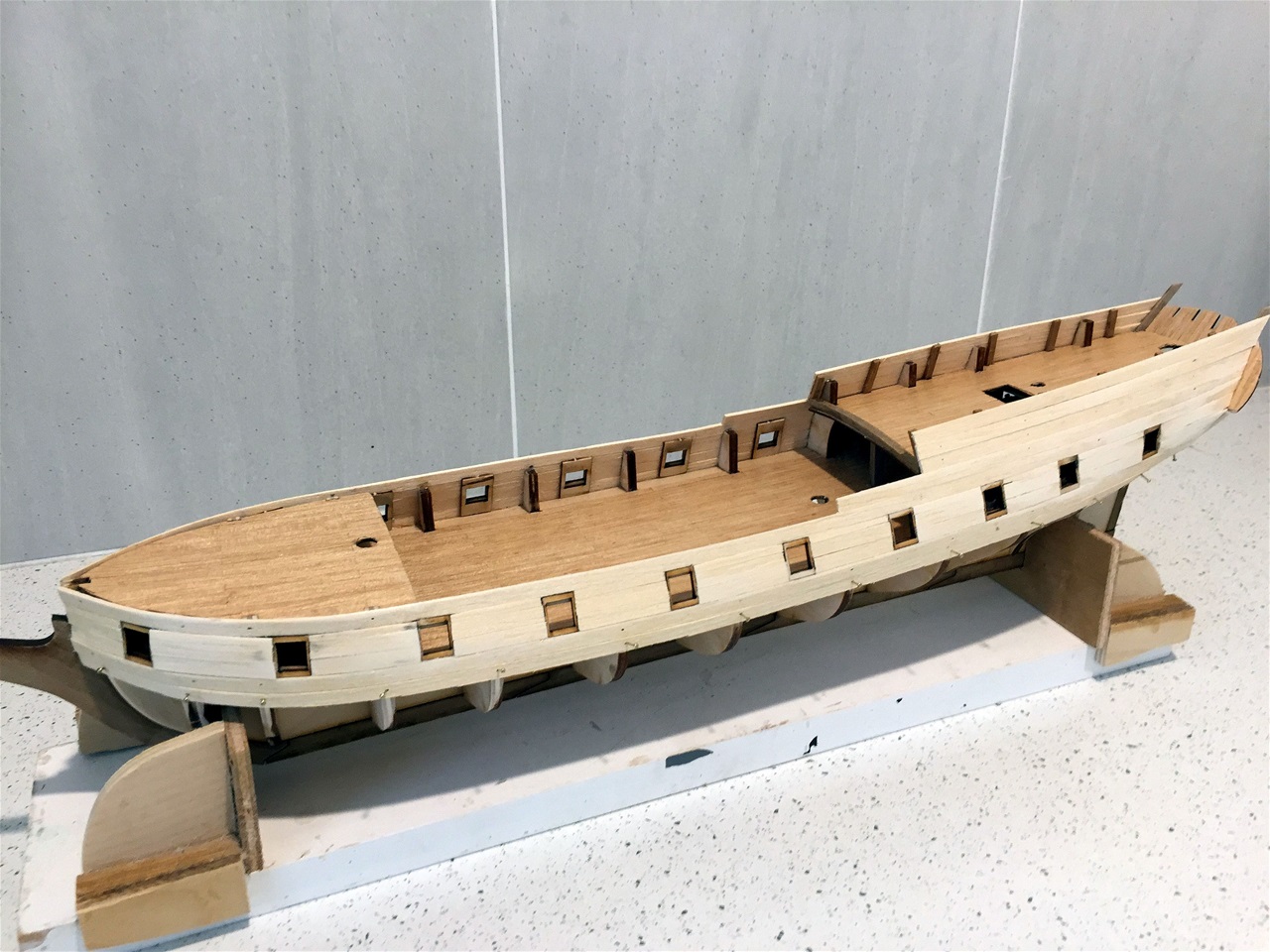
All hull planking complete
Beside all the hull planking being completed, further work has been done on the bulwarks. The internal sections between the bulwarks and the deck level were all sheathed onto support posts equally spaced. The focsle bulwark tops were made using a template and constructed by joining 2x1 mm on ech side of a 2x2mm centre piece, glued together, bent to shape with a steam iron, placed overnight in the template and fitted next day.
A similar method will be used to duplicate the tops and placed on seven 2x2 mm posts on each side of the focsle deck, forming a safety railing. (see below)
Support posts for safety railing in place

These posts were delicate to make, using 2x2mm resting against the raised bulwarks and strengthened with wedges cut to reach about 2/3rds up the posts.The posts were then trimmed to ensure the heights were the correct height before the tops were glued in place.
It should be mentioned that the instructions advised a different method of constructing the top post rails. They advised advised 2x2 sections should be cut to fit between the posts with 2x1 secured on either side over the total length.
It was considered this method slow and would barely allow for height adjustments required to ensure they were level with the safety railings abrest of the focsle deck. As it so happened, the method adopted (as above) worked perfectly and the railings met prceisely at the bow. (see photo 2 below)
Overview of safety railings on poop and focsle decks.
These safety rails were fairly difficult to make using only 2x2, 2x1 and 1x1 for the intermediate cross rails. Each stage had to done separately and allowed to set. The posts were strengthened at the base but using shorter wedges than those used on the bulwark posts.
Bow railings complete 17.2.21
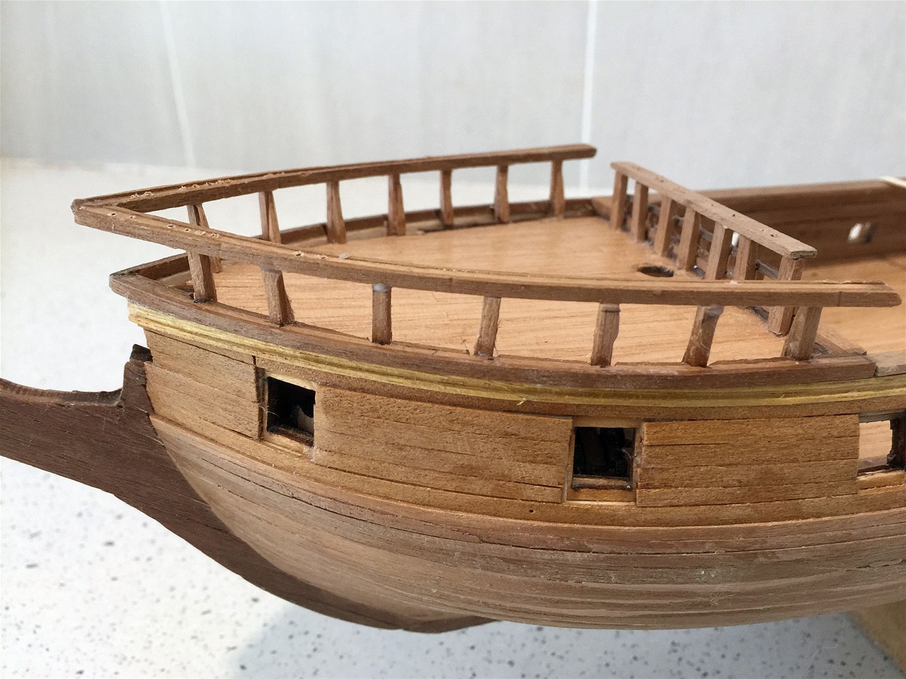
Showing the completed bow railings. The next step called for is the painting of the hull before continuing with the deck fittings.
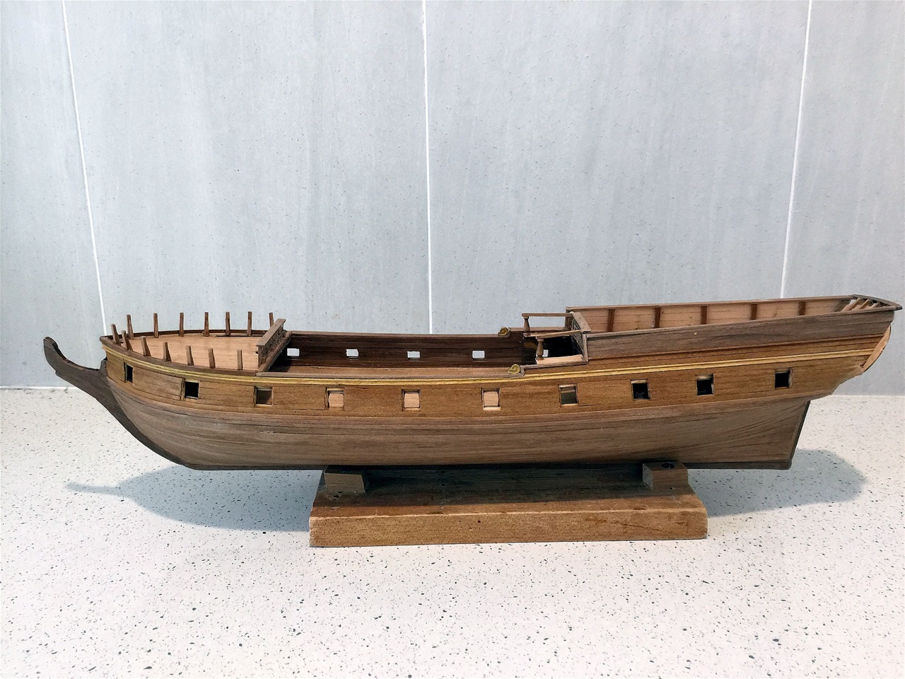
Side view of hull painting

This shows the hull painting whereby it was necessary to separate the three colours of the hull in turn, using masking tape. This was firstly applied above and below the three sheer strakes which formed the black line on both sides of the hull. After applying 3 coats followed by a coating of cabothane clear as a sealant', it was allowed to dry overnight.
The waterline was then marked and masking tape applied along its' length. The hull beneath the waterline was then painted white with three coats and one sealant.
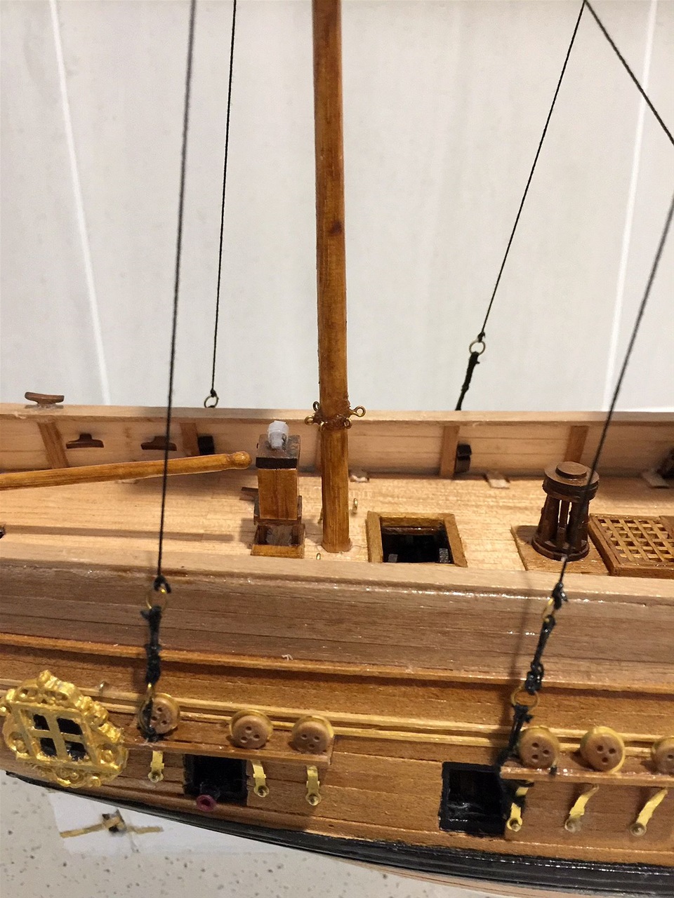
Poop dek fittings complete
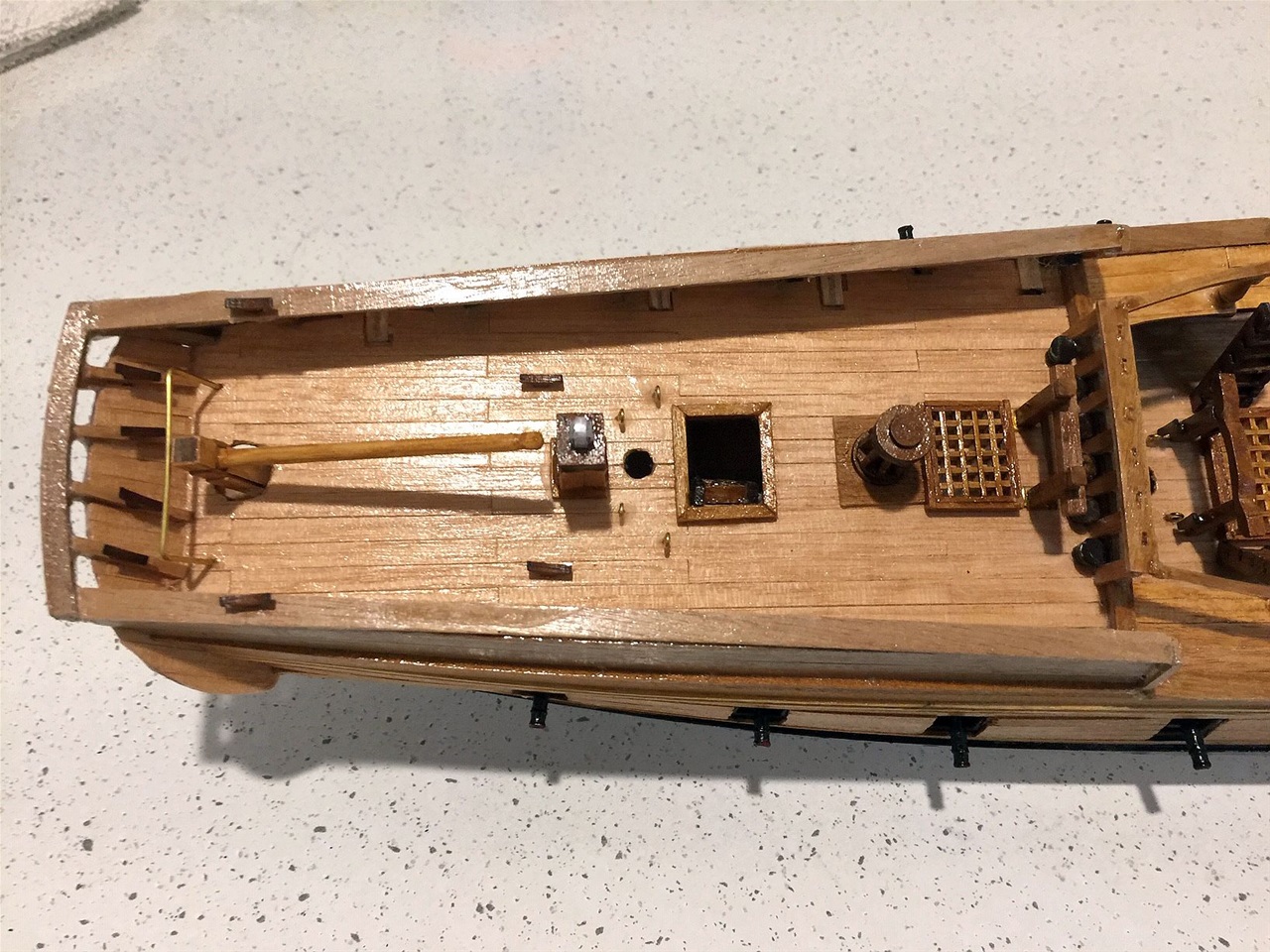
Because the deck fittings, in most cases, were extremely small & some with minute parts, progress was slow and laborious. Unusually, although shown on the part listings as being 'met' (meaning metal) and presumably molded, they were actually laser cut in timber.
The cleats, being in this category, were too small to insert a pin in the base and thus had to be glued, flat base to the deck, on the bulwarks and also horizontally on the internal planking beneath the bulwarks. Time will tell as to whether they wil 'take the strain' of the rigging when the time comes!! If they fail, then metal replacements will need to be purchased.
Note the binnacle just forrard of the tiller is an example of a complex structure on a very small scale as was the windlass forrard of the grating. Each of these were fitted with a small base plate (not required in the instructions) but considered necessary to ensure firm seating .
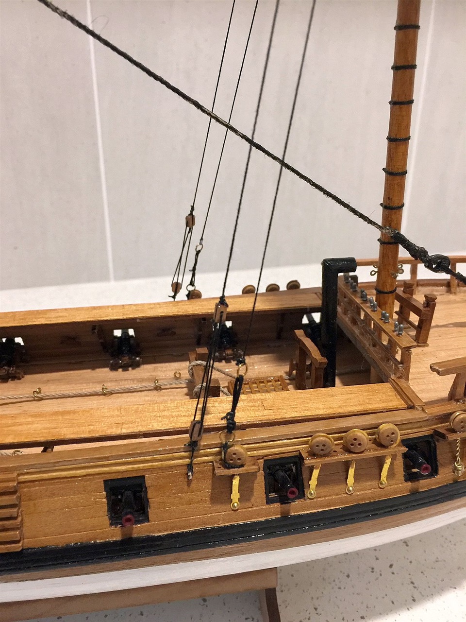
Midship section of deck showing fittings to date
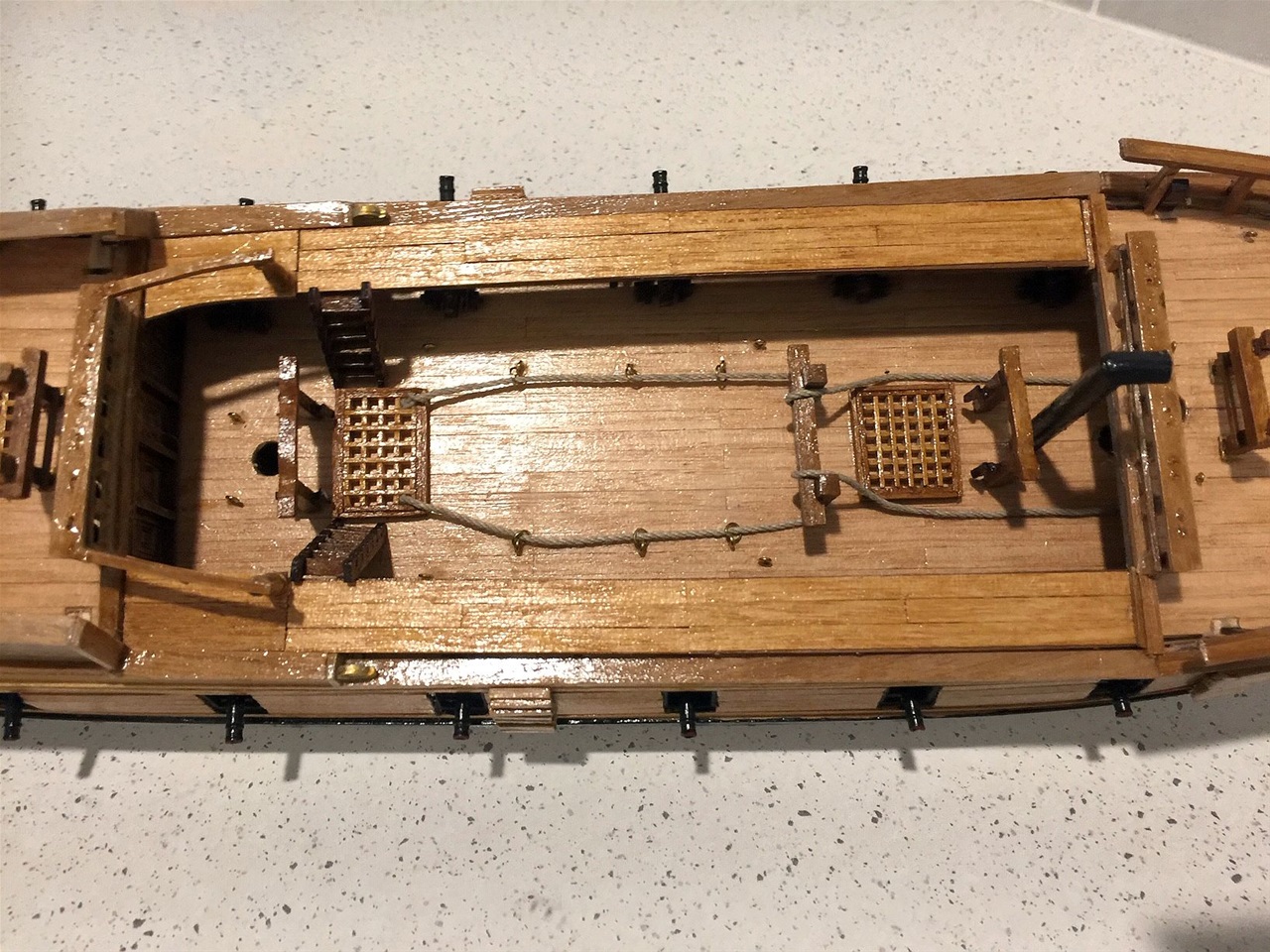
Some unusual features are seen here and it has yet to be determined what function the roping on deck does. The sets of bitts seen adjacent to the gratings at each end were fitted with pins on their legs as their dimensions allowed such.
More fittings have yet to be applied on this section.
Note: all the cannons have now been inserted on the carriages previously fixed in the covered decks fore and aft and now on the open midship deck
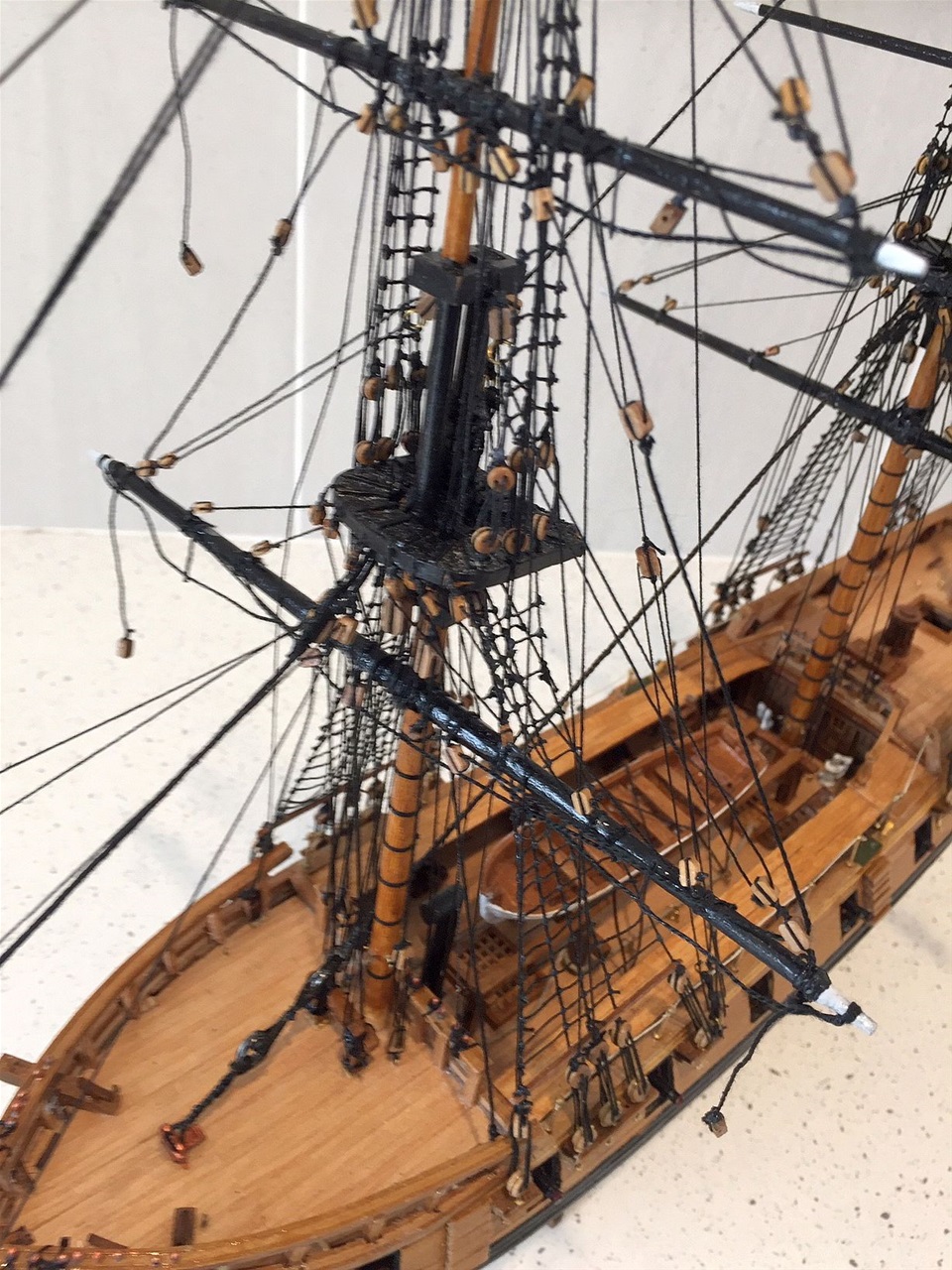
Basic rigging near completion
Battling along with conflicting diagrams to main plans, the rigging is proving to be an arduous challenge. Whether it is the style of rigging adopted by America of the time or of the kit designer who is reputed to be a very experienced one, is unknown at this stage and more research is needed
As is normal with rigging, it is commenced with the bowsprit and this model has 'plenty of it'! And this is before any of the later additions for the spritsail yards. Most of the lines have purchases using either dead eyes or blocks, both of the 3mm size. There is a prolific use of eye pins (ring bolts), brass rings and cleats attached to sprit topsail knee and the sprit top, both of which are very small components and liable for splitting!
View from port quarter

A view of the same condition from aft. Some details of the detail of minuteness of the basic rigging described above are shown in the following photos. At this stage of the construction, all the blocks and other attachments required on the masts have been attached as have the attachments around the deck area etc.
Bowsprit basic rigging
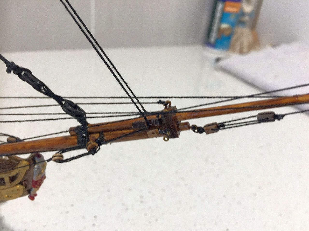
This shows the requirement of the very fine work required particularly on the spritsail knee and the sprit top whereby eyepins/ring bolts are secured to accommodate the purchases.
Foremast after braces
Here are seen the unusual methods employed to secure the braces on the outside of the hull with the main brace using base of the deadeye (where the shrouds will be attached). Next to it, the topmast brace is secured to an eyepin.
Detail of Main and Mizzen braces
Here is seen a duplication of the securing methods employed around the Mizzen. The brace on the right is for the Main topmast and on the left is for the Mizzen top.
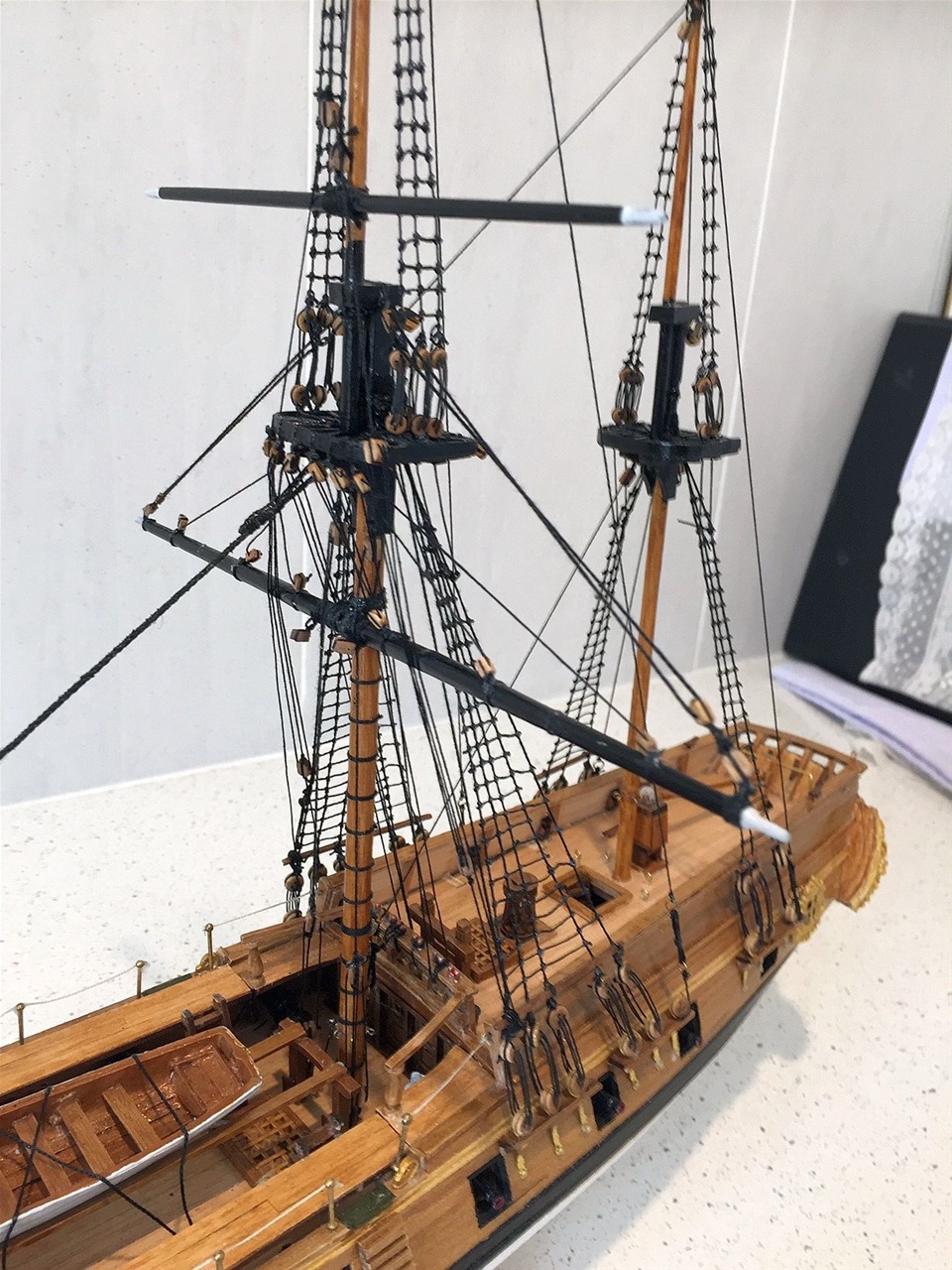
Basic standing rigging and lower ratlines in place
After some delays, progress was made on the standing rigging. Unusually the shrouds on the foremast and mainmast require a wide spread between the four forward shrouds and the fifth. When attaching the ratlines, they were only required to extend to the fifth shroud every second line. This made tightening of the ratlines somewhat difficult and it will be noted that there is some evidence of pyramiding, which was hard to avoid.
View from Starboard quarter

This view shows clealy the effect of "pyramiding" on the shrouds as mentioned above. It may be noted there needed to be a repositioning of the boarding ladders on both sides amidships. This was necessary as the extensions of the poop deck on either side were longer than the plans indicated and forced the ladders to be placed forward of gunport 6. Thus, to correct this, modifications were made to the length of the extensions to allow the ladders to be moved aft to the correct position.
Another modification was made to the 'portable' safety rails. The stanchions supplied in the kit, which were lead metallic, had a cup groove in their tops to accommodate a 2x1mm timber railing. They would not even accept a 1x1 mm so were replaced with brass stanchions from accumulated stock which were designed to take roping - far more suitable.
Foremast and bowsprit standing and running rigging closer view
A clear view of the "pyramiding" effect, particularly on the port side. Although the basic rigging is complete, there is rigging a-plenty still to do plus all the anchor details.
View of main and mizzen mast basic standing rigging
Here it can be seen the mizzen mast ratlines are allso inclined to be 'tapered' but the closeness of the shrouds at the upper areas allow little option! The view of the positioning of the alternative extensions of the ratlines to the after shroud of the mainmast, is more clear.
Full standing rigging and some running rigging partially complete

Having completed the basic standing rigging, the more complex standing rigging was commenced. The amount involved in this American built vessel requires agreat amount of concentration. The plans and diagrams provided are a maze of extraordinary detail and quite beyond those provided on previous models made.
Starting with the bowsprit, which is relatively 'delicate' in construction at it's forrard extreme, there are a multiude of braces using block and tackle. These all need space even though they comprise of 3mms blocks and 2.5 cottons. Thus they needed a steady hand when securing - and in the preparing process. Lost count was the time taken to finalise.
Partial view of bowsprit and foremast rig.
When complete, the rigging shown is most difficult to follow as there appears to be a duplication of many lines all of which are secured to almost inaccessable positions.
There are cluster of ring bolts on deck and around the base of the foremast which can only be reached by slender tweezers working in pairs - and certainly not by the average persons fingers!! There are belaying pins closely positioned on the bow rail as well as more on the forward rack. Nevertheless these also are so small that conventional securing had to be by-passed!
Foremast rigging complete except final running rigging
This close up shows the complexity referred to in the previous text. As can be seen, some adjustments will have to be made before completion of model is reached.
Main and Mizzen rigging partially complete
By working from forward to aft in rigging is a normal process and, on each mast, there are opposing views as to whether from top to base is the way to go or the reverse. Theoretically, the main yard is the largest, so the rigging is the most dense and should be completed first. That means the topmast rigging, which still has to be secured at deck level, has to carefully navigate the density ot the lower mast rigging. Thus, it should be better to deal with the lesser dense upper riggging first and then follow the procedure downwards.
In this particular situation, with such a high density of rigging, the latter procedure was followed. Nevertheless, in the latter stages and when attempting to secure lines in extremely 'busy' areas, some lines 'suffered' and had to be replaced.
All rigging complete and ready for final touch-ups.

The only attention left is to add the bunting to the mastheads, check out all the tensions and the shaping of all lines. In particular, the foot ropes on the yards which are easily disturbed when adding other lines. In this case, three had to be replaced following serious flaws.
All cleaned up and the bunting flying
The last job, after touch up painting and sealing, was to rig the hoists for the flage/pendants.
Using very fine (0.15) cotton posed some problems at the last post! The lines needed to be secured to cleats on the deck and these were surrounded by previously secured rigging. Time and patience was the neccessity!
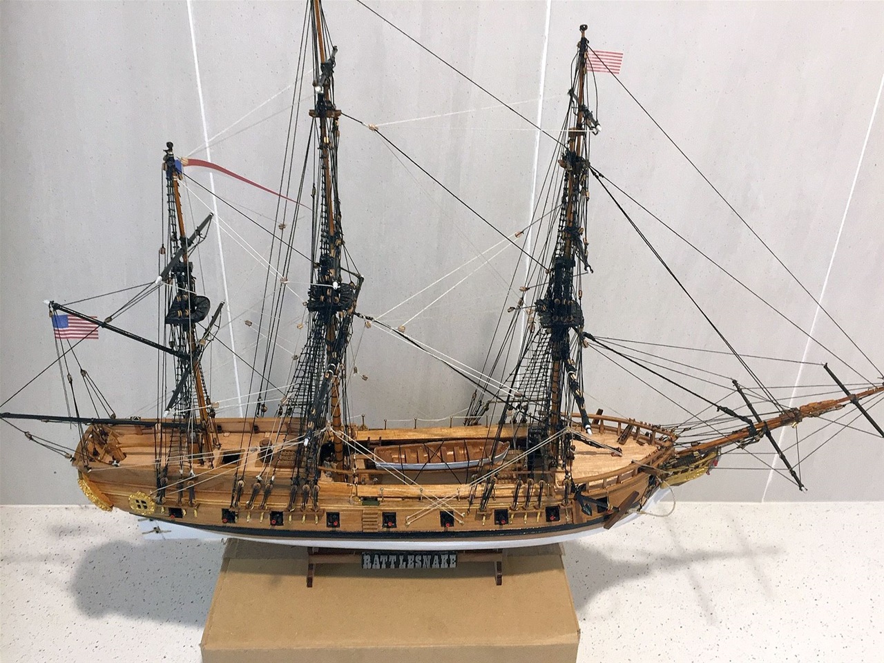
All done and ready for boxing up for display
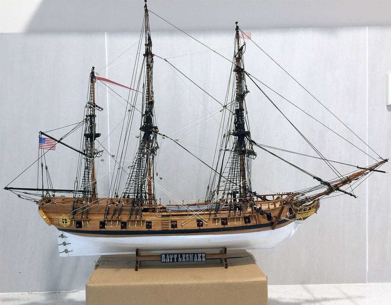
The name, the bunting flying and all the touch-ups complete. The model is now ready for display on base plate and perspex cover (both to be ordered dependant on covid restrictions!).