Classic Ship model No 29
The History of Cutty Sark
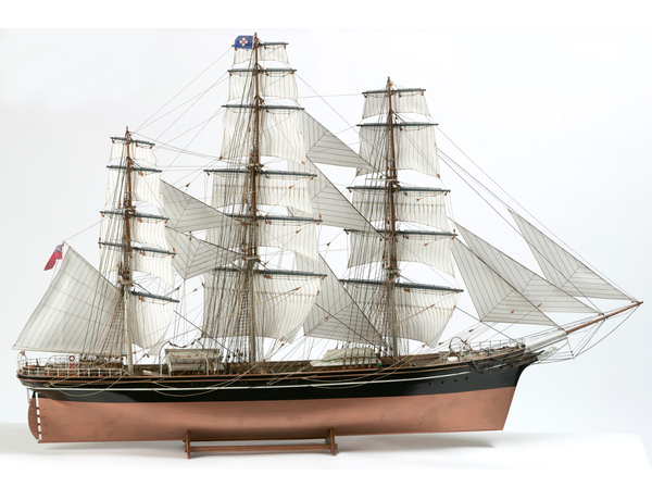
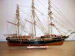
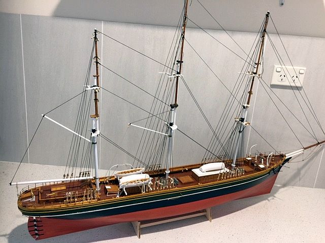
A Bilingboat photo of completed model
Considered to be the finest clipper ship ever built, the ship itself still resides in drydock in Greenwich, on the Thames. Having been damaged by fire on two occasions, the first in May 2007 when undergoing maintenance and the second - a smaller outbreak in 2014, she was restored and now continues to be open to the public.
Under the ownership of John Willis of the Jock Willis Shipping Line, the Cutty Sark was laid down in early 1869 by builders, Scott and Lincoln on the River Leven in Dumbarton, Scotland. She was launched in the same year and went into service on February 16th 1870.
General Specifications
Tonnage: 963 GRT Displacement: 2,100 tons Length Overall: 280 ft
Beam: 36 ft Class and type: Clipper ship 1870-1916 then Barquentine rig
Sail area: 32,000 sq ft Maximum speed achieved: 17.5 kns Crew: 28-35
Note: the competition, as mentioned below, between the Cutty Sark and the Themopylae is briefly recorded in this website under the Thermopylae header.
In service - the Cutty Sark at sea
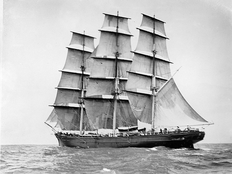
Photo by courtesy of Wikipedia
The vessel had been designed for the tea trade with China in direct opposition to the earlier built Thermopylae which was acclaimed to be the fastest afloat at the time. Built earlier, in 1868 she had set a record of 61 days, port to port and it was such record that Willis was determined to beat. Various proven superior designs of stem and stern were fitted and the hull made from elm in the keel and planked in teak. The frames were of wooden panelled iron frames in lieu of the more bulky oak. The ship construction was supervised by Captain George Moodie who was to later command her.
Work was suspended when Scott and Linton ran out of money and arrangements were made for William Denny & Brothers took over. Eventually, on the 16th of February, 1870, Cutty Sark saild from London with cargo for Shanghai, returning with tea and arriving in London on the 13th October 1870 via the Cape of Good Hope. She then sailed in eight tea seasons to China but, with the advent of the opening of the Suez Canal and the entry of steamships on the trade, she turned to the wool trade with Australia.
Here, she excelled with many speedy voyages over the years until, in 1895, she was sold to the Portuguese Firm of Joaquim Antunes Ferriera and was renamed "Ferriera". She carried various cargoes on voyages from Portugal to the Americas, E Africa and Britain.
Following a successful period with the new owners, in 1916 she was damaged in a storm off the Cape of Good Hope and replacements to the masts were impossible to obtain. As result, she was re-rigged as a barquentine and finally in 1922 she was obtained by a Captain Wilfred Dowman with a view to becoming a Merchant Naval training vessel. This was achieved and, after his death, the ship was handed over to join the Thames Nautical Training College HMS Worcester at Greenhithe. Her final resting place in drydock for preservation by the Cutty Sark Preservation Society was in 1954.
The Model - Clearing the decks
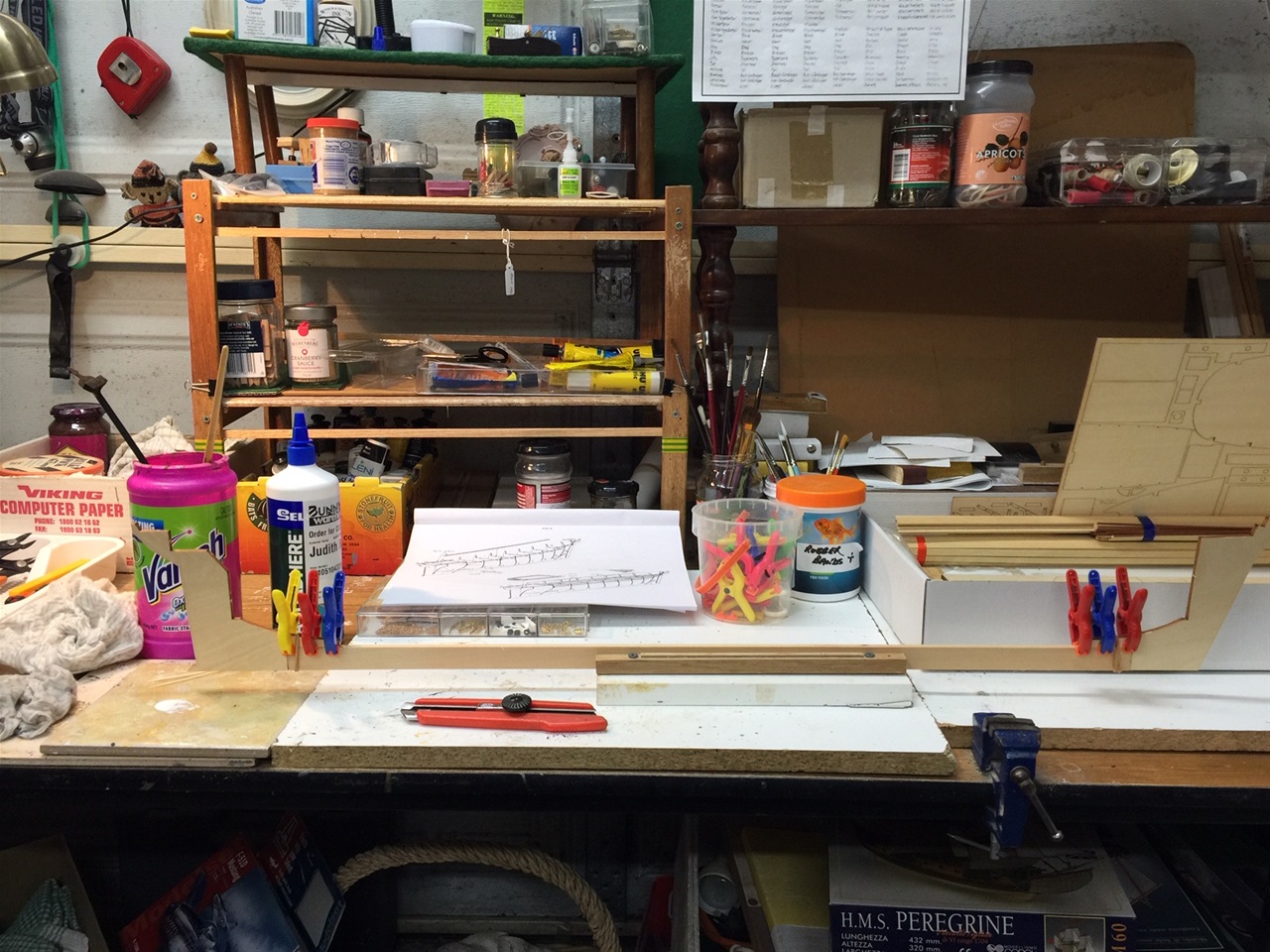
This model of the Cutty Sark is 1:75 and is delivered in a box well over 1 metre in length. Although unclear in the enclosed documents, it is no model for a beginner! The first thing to perform is to open up the contents and check everything . However, there are so many small parts all mixed up in plastic sealed bags without any reference to the numbers of the parts (many hundreds). The best one can do is to seperate all the like objects and place them in containers such as the ones provided by many of the other model makers. The unlike ones can be placed together and hope they can be recognised as the construction moves on!
The 'Building Instruction' booklet, written in eight languages but with only one page for each, is brief to say the least. One has to carefully examine each of the following pages where there are many sketch/diagrams of various assemblies but with minimum explanations and many arrowed lines. These pages are then followed by 9 pages listing over 100 parts and a similar number of each individual pieces of varying timbers used throughout the build.
Finally, there is a large double sided overall plan of the completed model - both overhead and side profiles which helps a great deal.
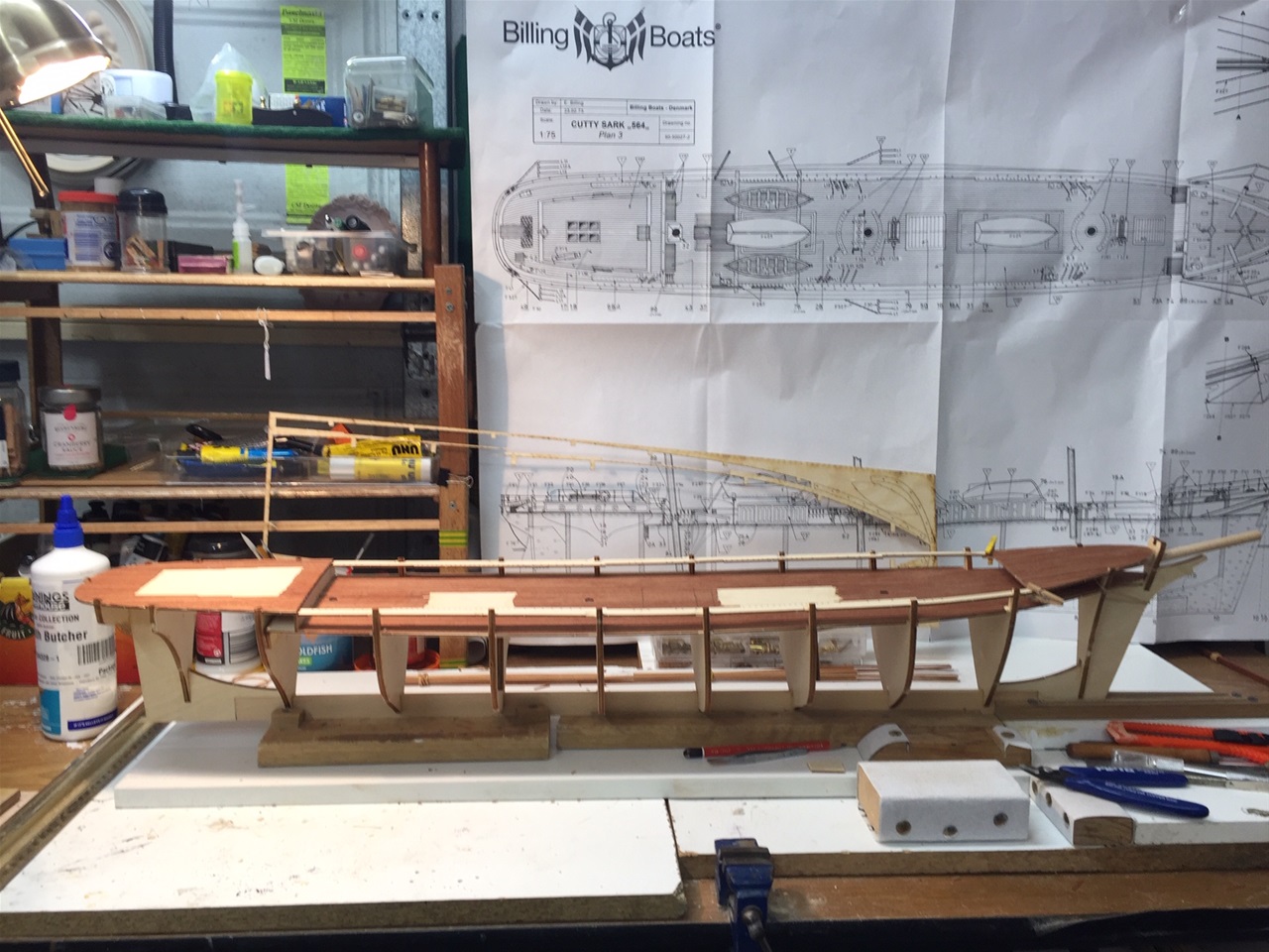
To start the model, it is essential to 'clear the decks' of the workspace as this model needs plenty of room to work with! This photo shows a cluttered area before clearance! Be prepared to do a great amount of cross referencing throuhout the build!
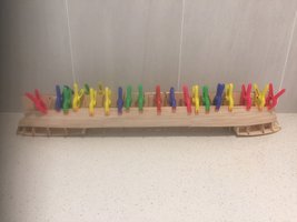
The keel construction - the first join
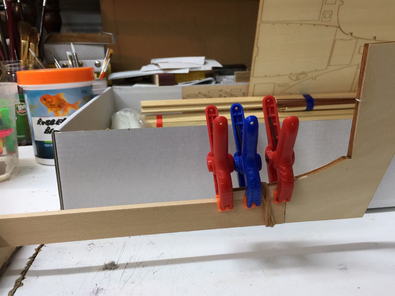
Whereas most models have laser cut outs of the keel marked with grooves for positioning the frames. Not so with this model. The keel comes in three parts - bow end, after end and a straight timber centre length.
The photo shows the first join of the keel with the bow section - glued and clamped until dried.
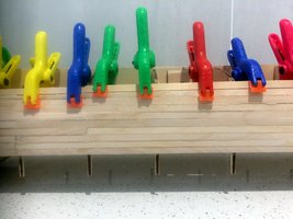
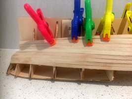
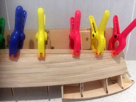
The keel construction - second join
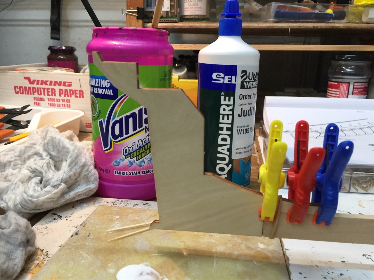
This shows the joining of the stern section with the keel - glued and clamped until dried
Frames in place - specific distances between
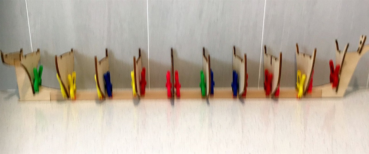
The frame spacing is shown on a small diagram in the booklet. However, when adding up the toatl, it failed to match the distance on the model beteen the firsy and last frames. After some deliberation it was realised the plywood main deck cut-out would have the necessary slots to accommodate the frames, and this was the answer. The bulwark cut-outs were similarly such.
Longitudinals strengthers fitted to frames
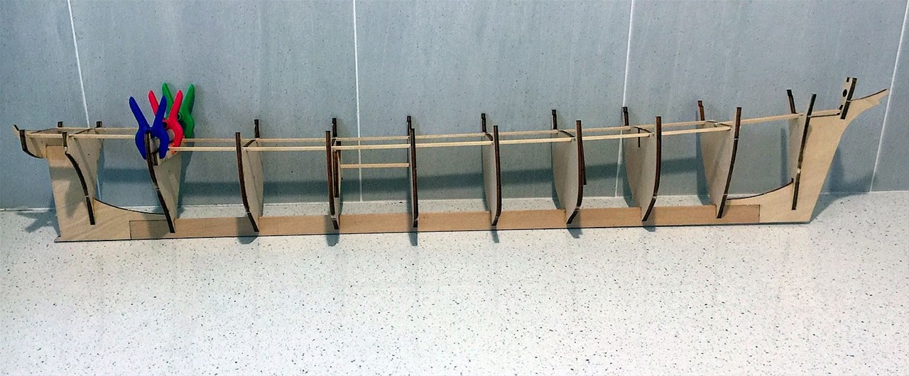
After the gluing of the frames to the keel plate, it is necessary to insert the two longitudinal strengthners and the underdeck stiffeners. Then the deck cutout can be placed and glued.
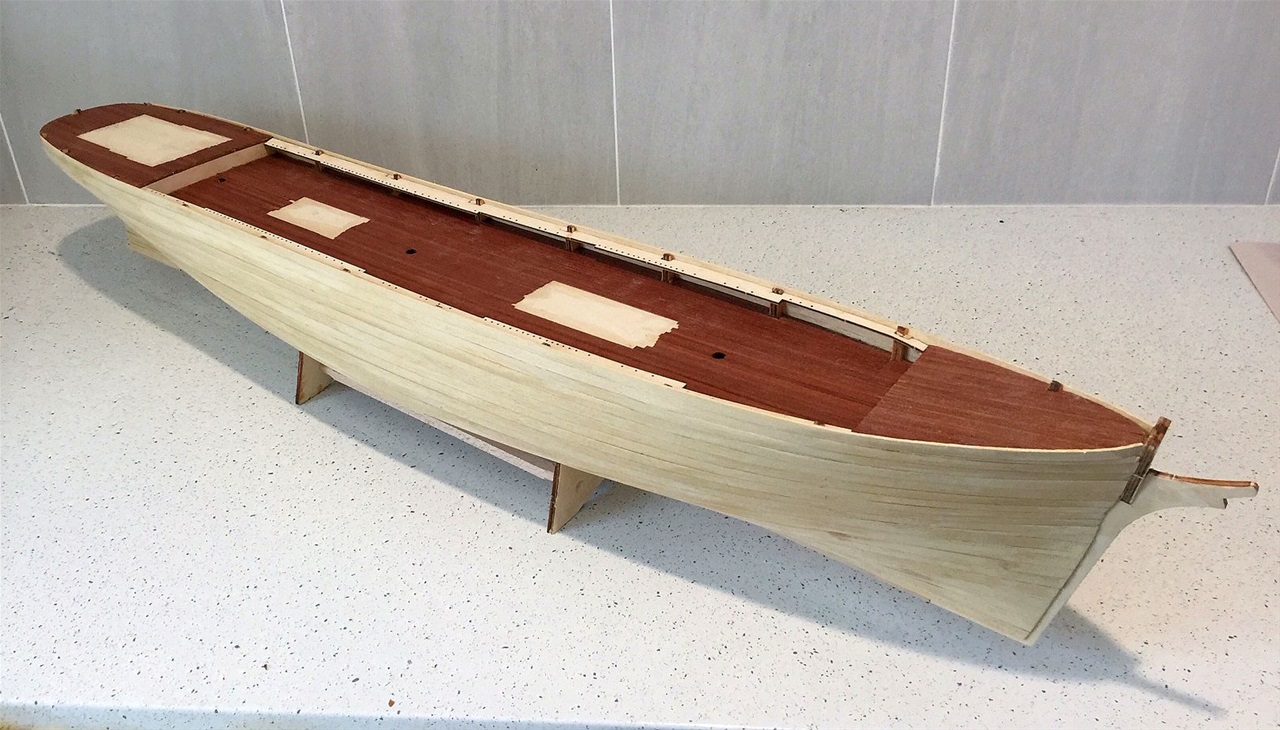
Deck cut-out in place and the deck planking part complete
With the deck planking almost complete and the bulwark tops glued on to the frames, the process was now in a position to proceed.
Deck planking complete
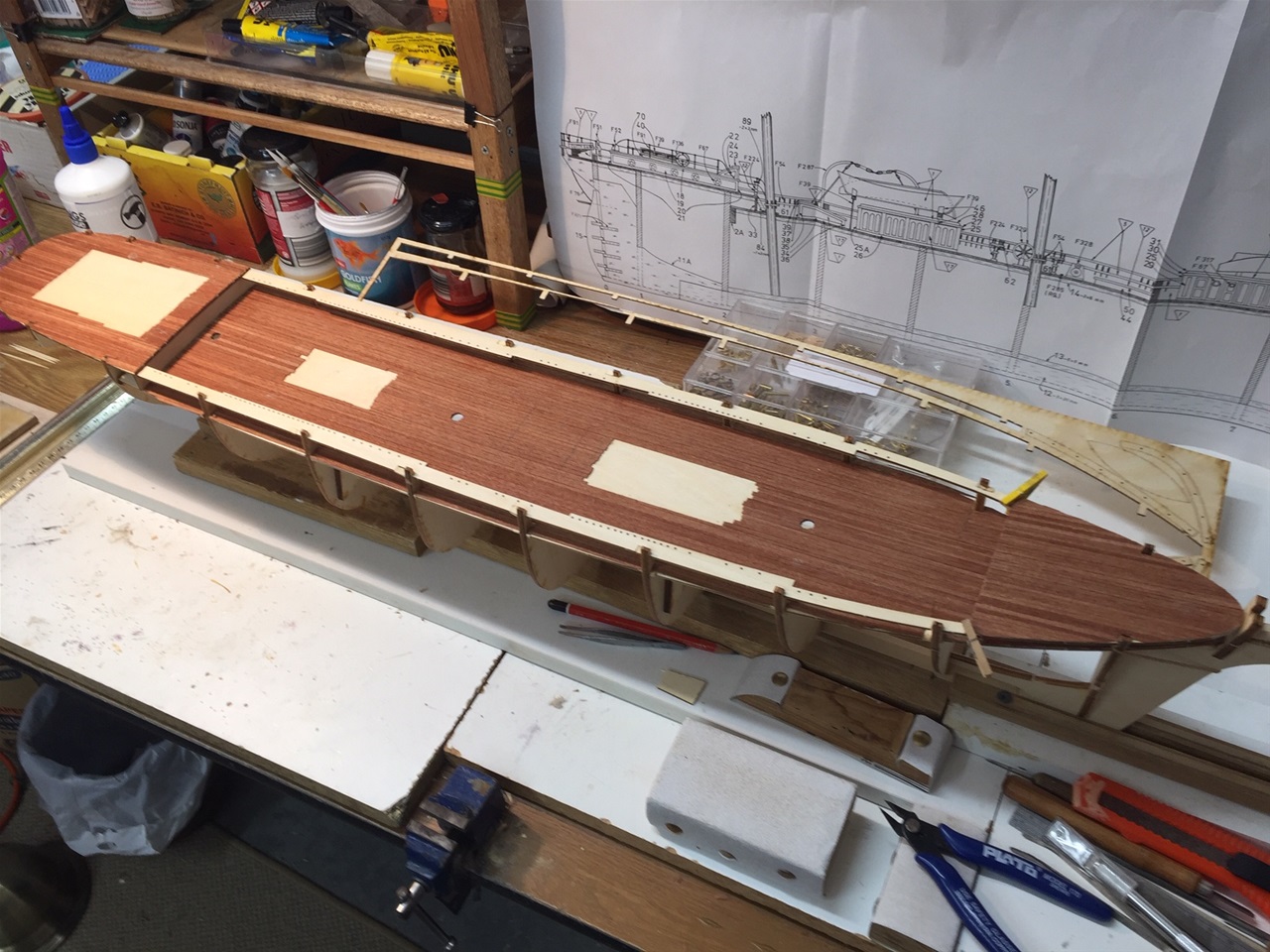
It should be noted here that deck planking provided seemed to be on the border line for being insufficient. Hence it was decided to mark in the positions of the main deck houses and not cover them except for an overlap to provide a level to deck surface for the houses. As it happened, on completion this way, only 4 lengths of decking remained. As the outer deckheads of the deck houses are slated to be decked, an alternative planking will be obtained from stock. Unlike most other models where the planking were shortened to common lengths and then laid brick like fashion. these planks were required to be laid full length wherever possible.
AS the next step will be the hull planking, it was decided not to add anything further at deck level as it may be necessary to invert the model at some stage. However, the deck should be sealed and the stern balsa blocks provided should be trimmed and shaped according to the plan. They are then glued in place. The broader squarer stern was designed by the owner to provide a better bouyancy in heavy stern seas and protection for the helmsman etc.
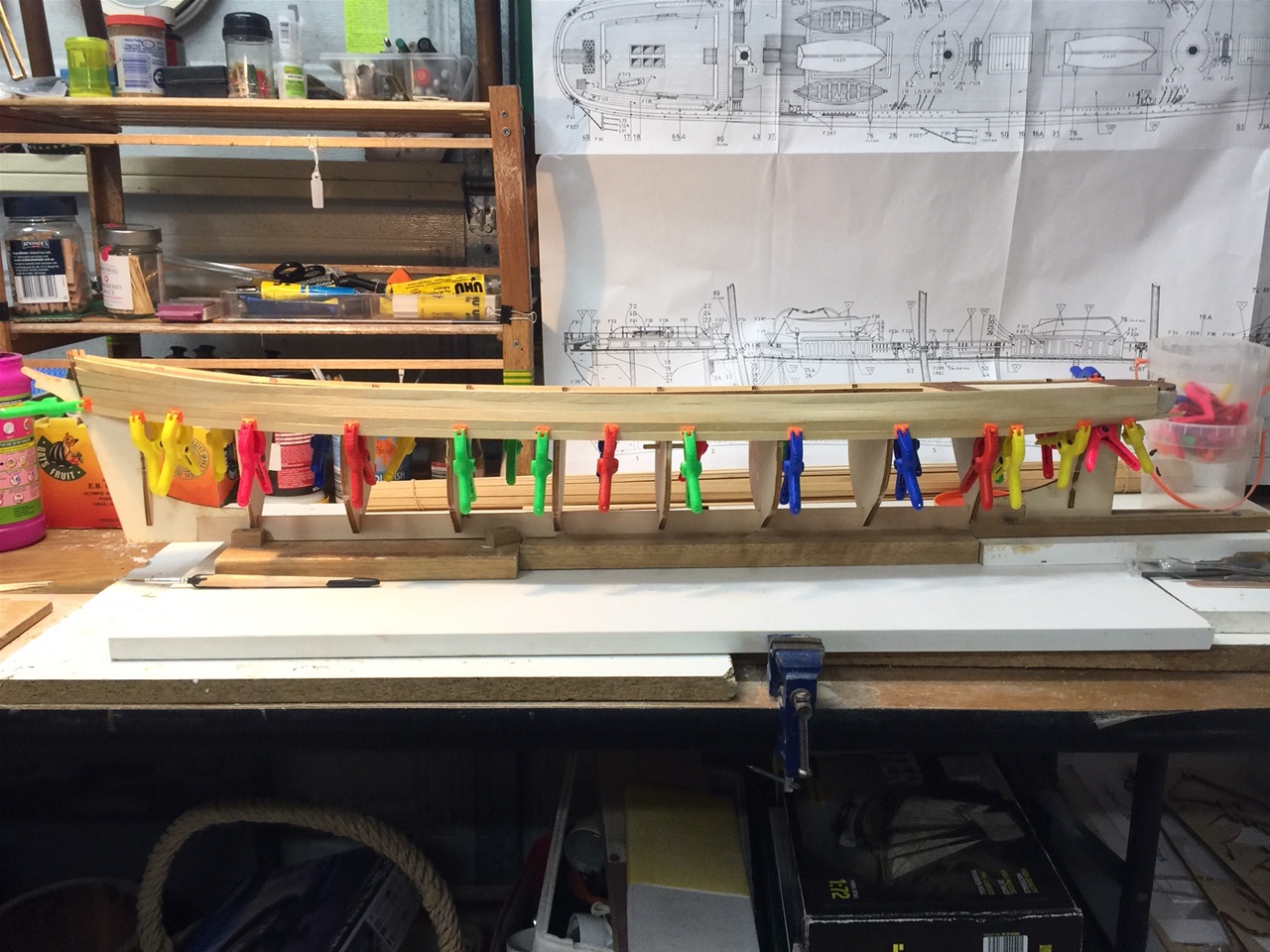
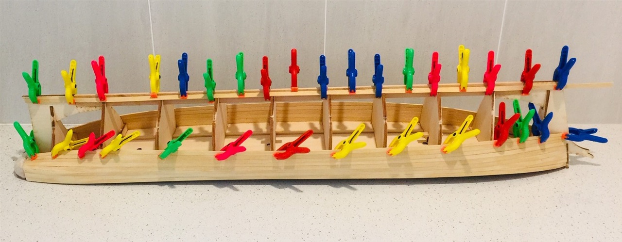
Ist hull planking
The model has single hull planking only. As usual, the planking is done alternately one port, one starboard side throughout and this shows the first planking laid. This is the most important plank of all and it must be assured that all the frames have been sanded flush with the deck line from forrard to aft and the first plank adheres to every frame for the full length. Due to the relatively long sections (circa 800mms of 1.8x7mm Obechi wood) it was flexible enough to glue half the length and then clip before glueing the second half and clipping. The forrard end needed little bending and was handled easily with the steam iron! The after bending was minimal.
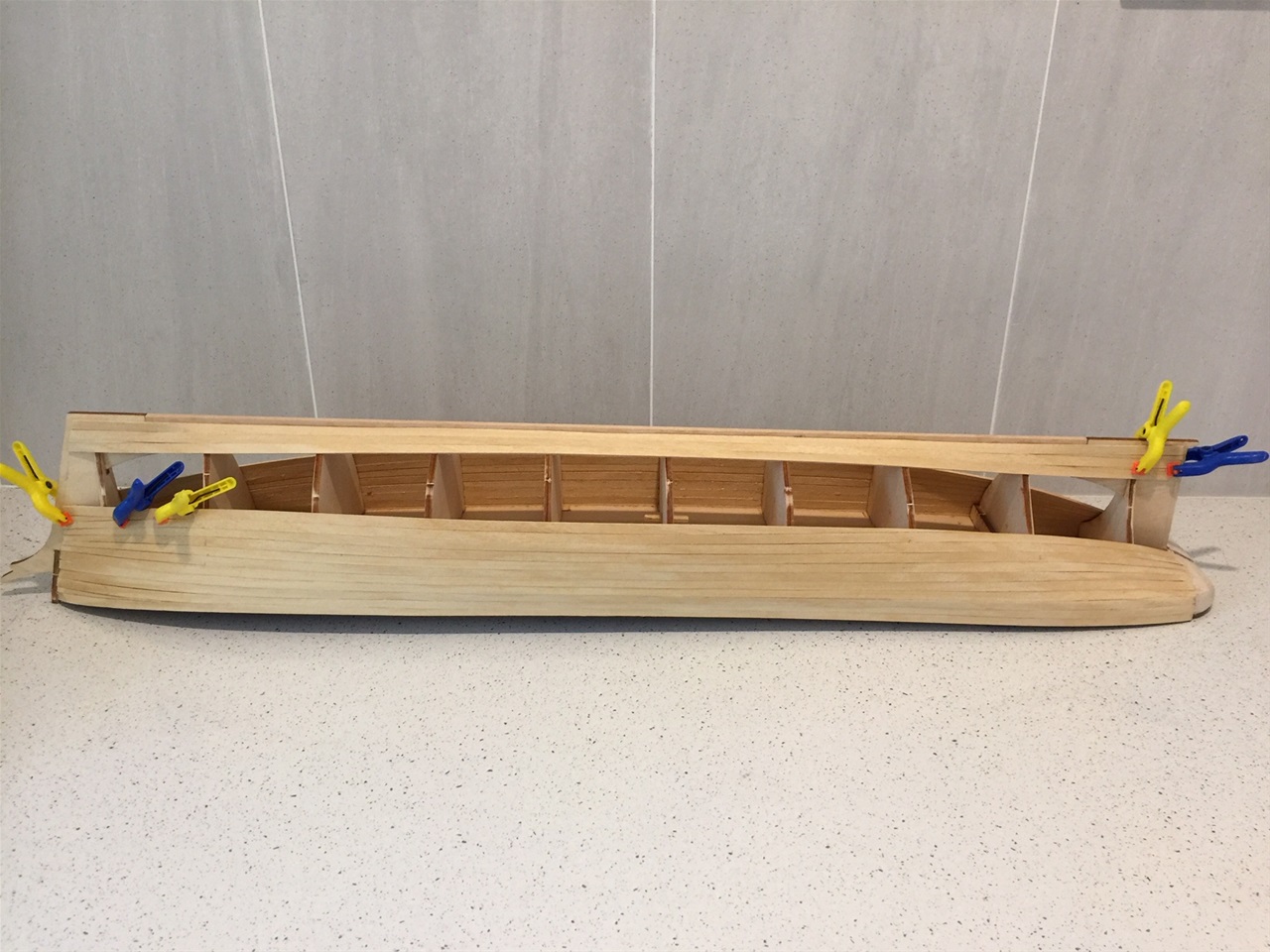
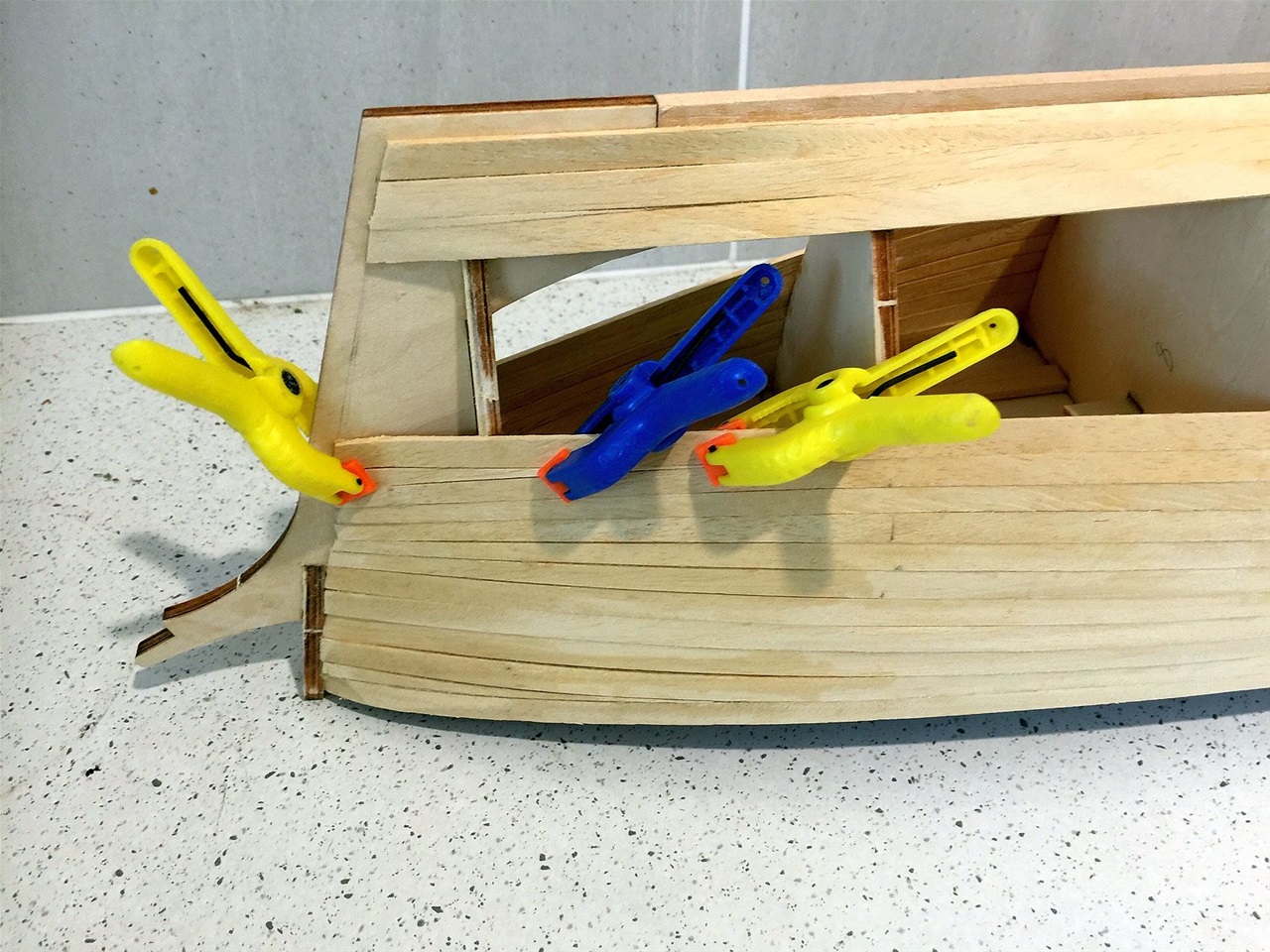
4th planking in place
The second planking was required to feature a wedge at the bow although it didn't really seem necessary. It was, however, inserted and progress continued on the basis of two planks per day (1 on either side of course) until the fourth was completed.
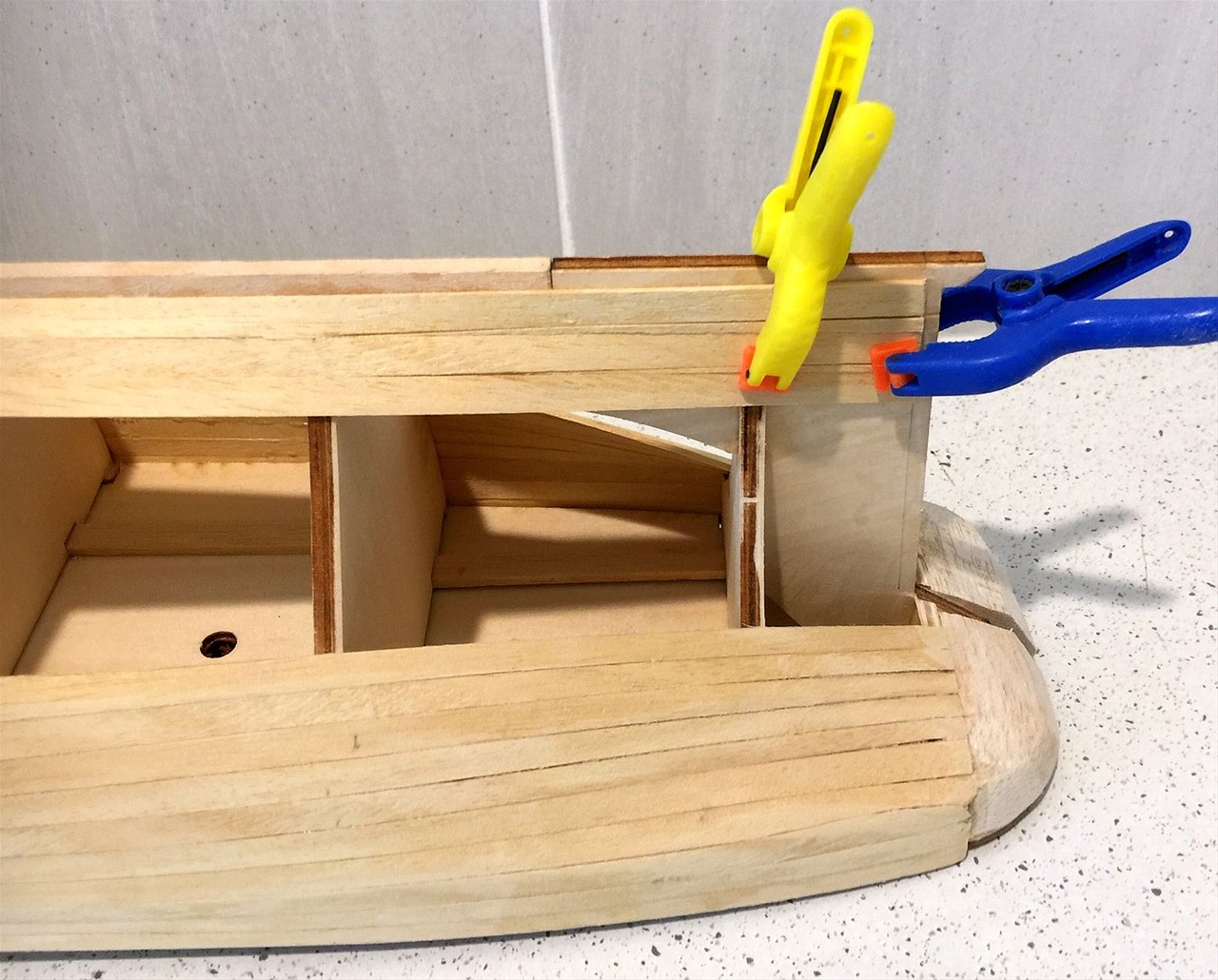
When the third planking was laid, it was found the stern end needed careful attention as it was the where the transom was 'undercut' = thereby requiring the planks on both sides to be trimmed to half their width and bevelled for two frames length from the stern. Further fine sanding was needed to line up with the solid balsa stern. After this, the fifth plank and most planking after this will need reducing in width at both ends and bevelling to be done to take account of the tumblehome and flare.
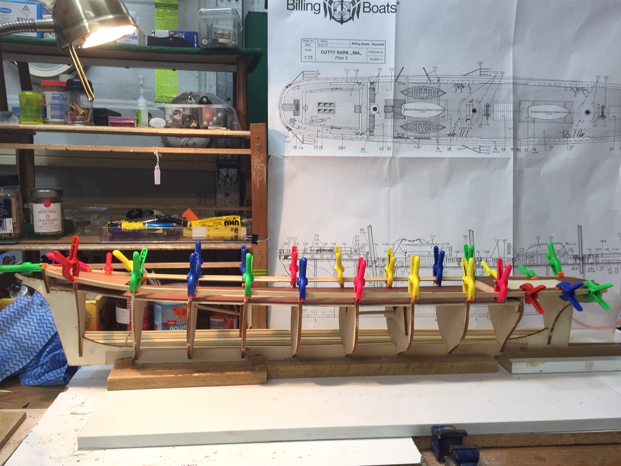
Starting from keel
After 8 planks had been attached to both sides, from the deck down, it was time to start from the deck upwards until a 'midship' position is reached on the hull. This photo shows it with such planks in place.
Halfway planking reached
With 11 planks set from the deck and 3 up from the keel, it was recognised as being the 'halfway mark! At this stage it was found there was a slight shrinkage appearing in isolated spots. No doubt it was due to the bending process using the steam iron which does produce some dampening. A lesson that the planks must be left to dry completely before insertion.More care was taken and with a continuation of bevelling, the problem was under control.
Having been calculated there would be 21 planls required on each side plus the tapered sections at the 'meeting point', this was the halfway point.
Wedges required forrard.
At this stage, wedges need to compensate for the gaps at each end of the planks which need to laid 'as the timber wants to go' - as the advisers passed on in the early days. There comes a point at which the planks refuse to 'bend and twist' at the same time!
Wedges required aft
As can be seen, wedges are required at the after end also.
Basic planking complete
The planking was completed on 12/10/21 thus indicating the finalisation of Stage 1 of the project. With fine sanding and some light 'filling' where necessary, It transpired there was a need to insert two tapered planks at the 'meeting point' plus a filling with'slivers' in the odd places which fortunstely blended in to produce a smooth surface.
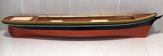
Painting completed of upper hull
After some research of photos, paintings and models of the ship, plus the colours shown on the box, it was decided to adopt the following.
The two upper strips of 2x2mms and the edge of the bulwarks would be painted in yellow ochre and the lower third strip would be in white. The intermediate planking would be in olive green. In the majority of cases seen, tradition called for them to be in black as per the rest of the hull to the waterline. However, it was decided the blending of the ochre and the olive green - similar to the 'Nelson' preference - would provide attractive contrast blended with the black. After a coat of sealer, on completion of this section, it is actually hard to distinguish the difference.
Note: the Josonja acrylic Olive Green paint was used on the "Thermopylae" and most people thought it was black when dried when it was supposed to be similar to the green used on the clipper itself.
At this stage, a coat of clear sealer was applied prior to commencing the red painting of the 'under waterline' section.
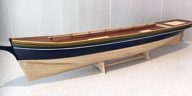
Boot Topping complete
Following the success of defining the waterline with masking tape and the black cut being almost fault free, it was then necessary to place masking tape above the waterline by following the edge of the black painted section. Ample time is needed for drying of the black before applying the tape and between 24 and 36 hrs is advised. As the black had been sealed with clear sealant when it had been dried, then a further time spell elapsed before the boot topping was applied.
Deciding the colour for the boot topping again relied upon research combined with personnel preference. The actual vessel in Greenwich has the coppery gold look which reflects the hull treatment of Muntz metal (an alloy of zinc and copper) as mentioned in Sir Basil Lubbock's thorough research into the original Cutty Sarks paint jobs, in his document "The Log of the Cutty Sark".
The Billingboat kit recommends red - which had become the favoured colour of later model vessels - so this was chosen as it does look great in its' contrast with the black upper reaches.
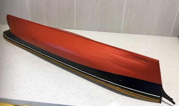
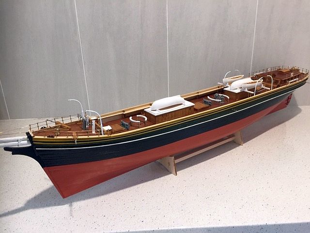
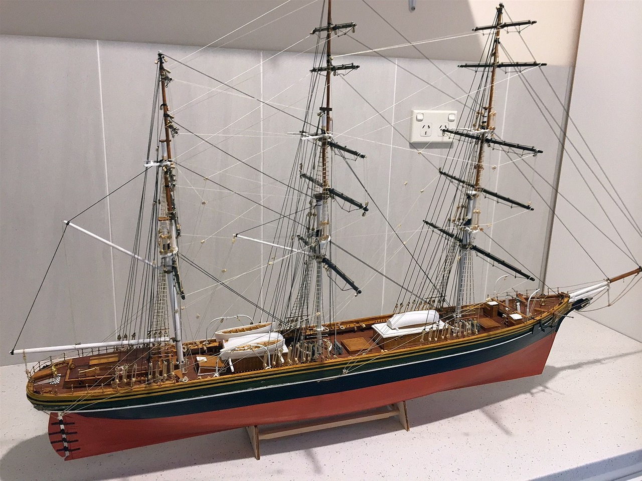
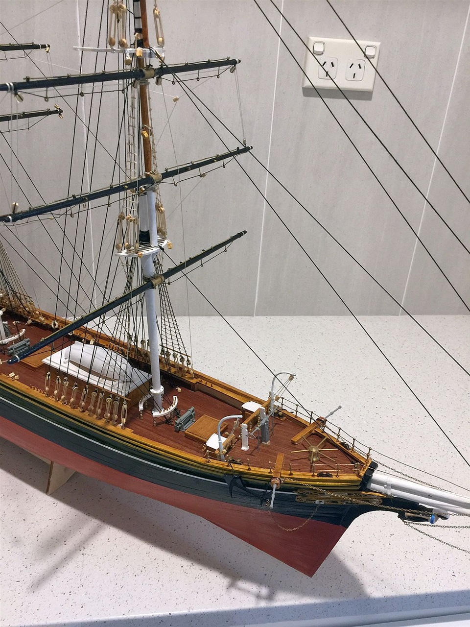
Painted Hull in Profile
This shows more clearly the attractive contrasts between the various hull colourings and the beauty of the lines of the vessel.
It is now time to move to the deck fittings which are vast and complex to follow in the plans and instructions
Basic deck fittings complete
After many hours of toil, the basic deck fittings are in place. Fundamentally, a start was made on the foredck then gradually working towards the stern. However, it made sense to assemble the pumps and other 'metallic' items together but generally held back for final postioning until other major deck houses etc were positioned.
Checking and rechecking the exact positions were vital as so many eventualities had to be considered, such as clearnce for mastings, belaying pin racks etc.
Overall view of deck from aft
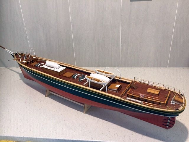
The after deck was probably the most difficult area as it needed an analysis of the sequence of work. As an example,the deckhouse had to have portholes fitted before being secured and before the deck railings were sited and wired up. as there was very limited space between the two.
Foredeck close up
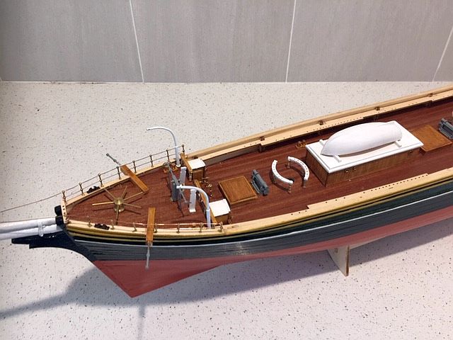
A fair amount of care had to be taken here as the measurements between the appliances had to be accurate to allow the functioning of the individual items. Again it was a question of sequence and accuracy.
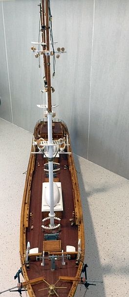
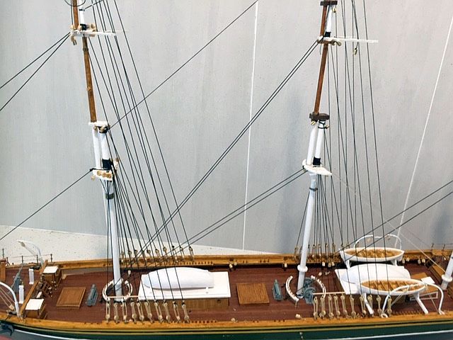
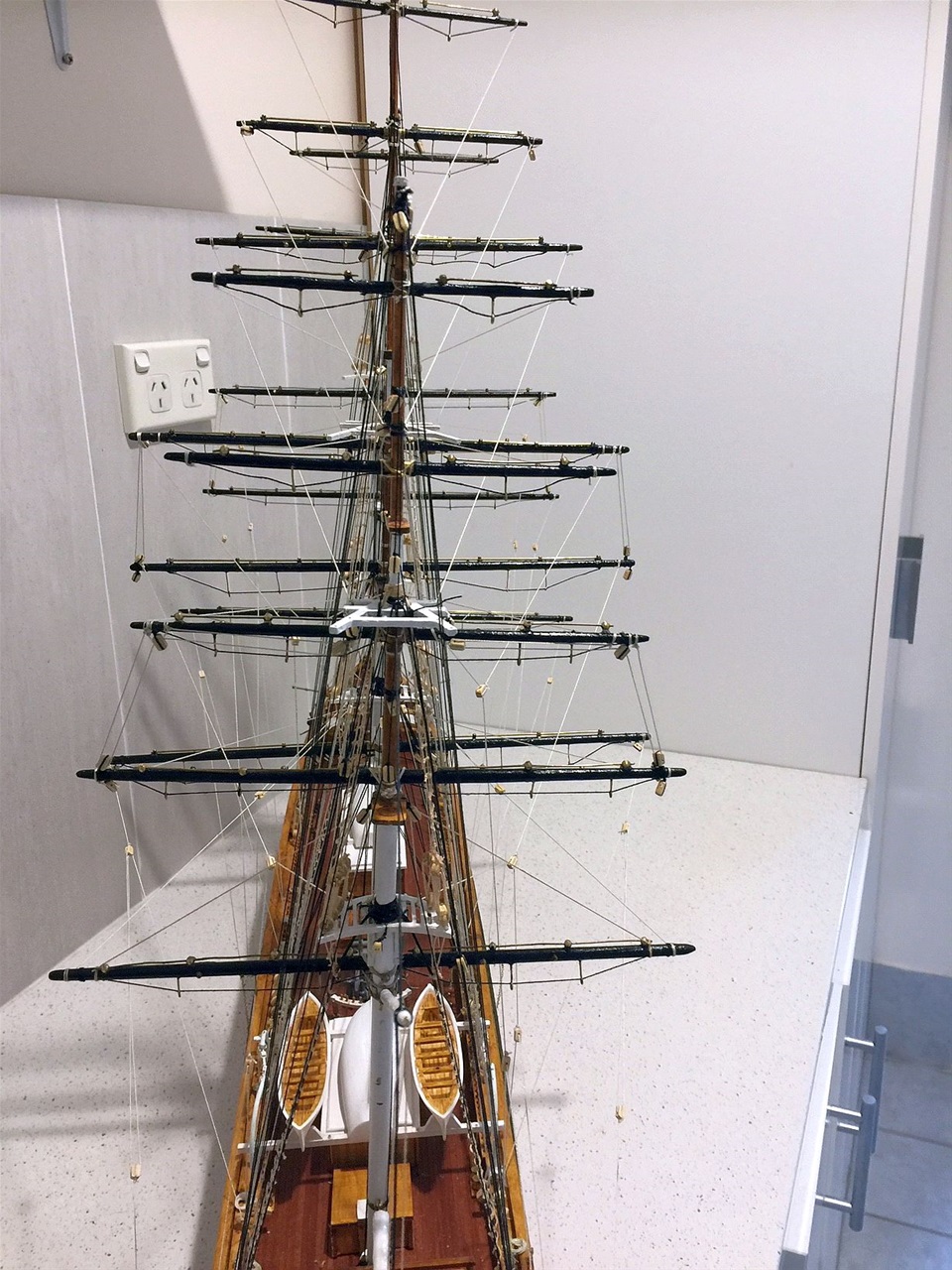
Midship section
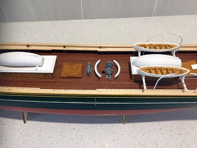
This shows the lifeboats in place on the top of the deck housings. The forrard one(on the left of the photograph) was straitforward, being mounted on two beams astride of the roof but the after three wre more complex. Two longer beams were used but the forrard beam sat mounted on supports just forrard of the housing. The ends of the beams were also supported by brass wire struts into the bulwarks. The outer boats were fitted snugly into timber cradles secured to the beams.whilst the uptuned craft in both cases are sitting on their own gunwales, on the beams.
The four davits were then posioned in their correct spots for the launching process.
Close up of poop/quarter deck arrangements
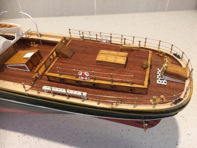
This shows the limited space between the deck house and the outer rails plus the inclusion of the belaying pin racks as mentioned earlier. Note the wheel mounted on the small housing on the after railing, where the helmsman stands on a chequerboard pad on the deck. A unique creation for most, we guess.
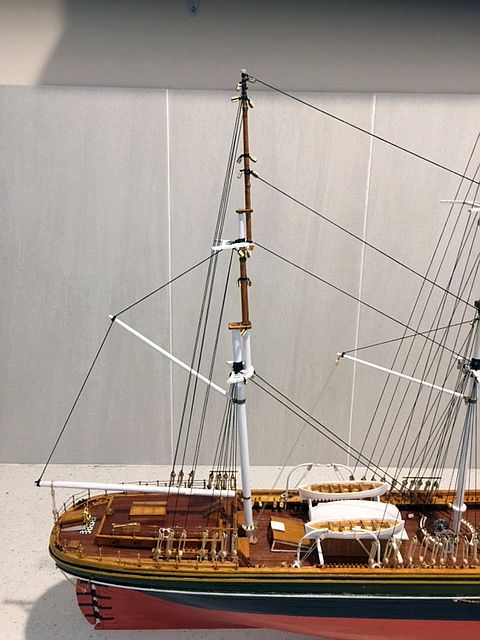
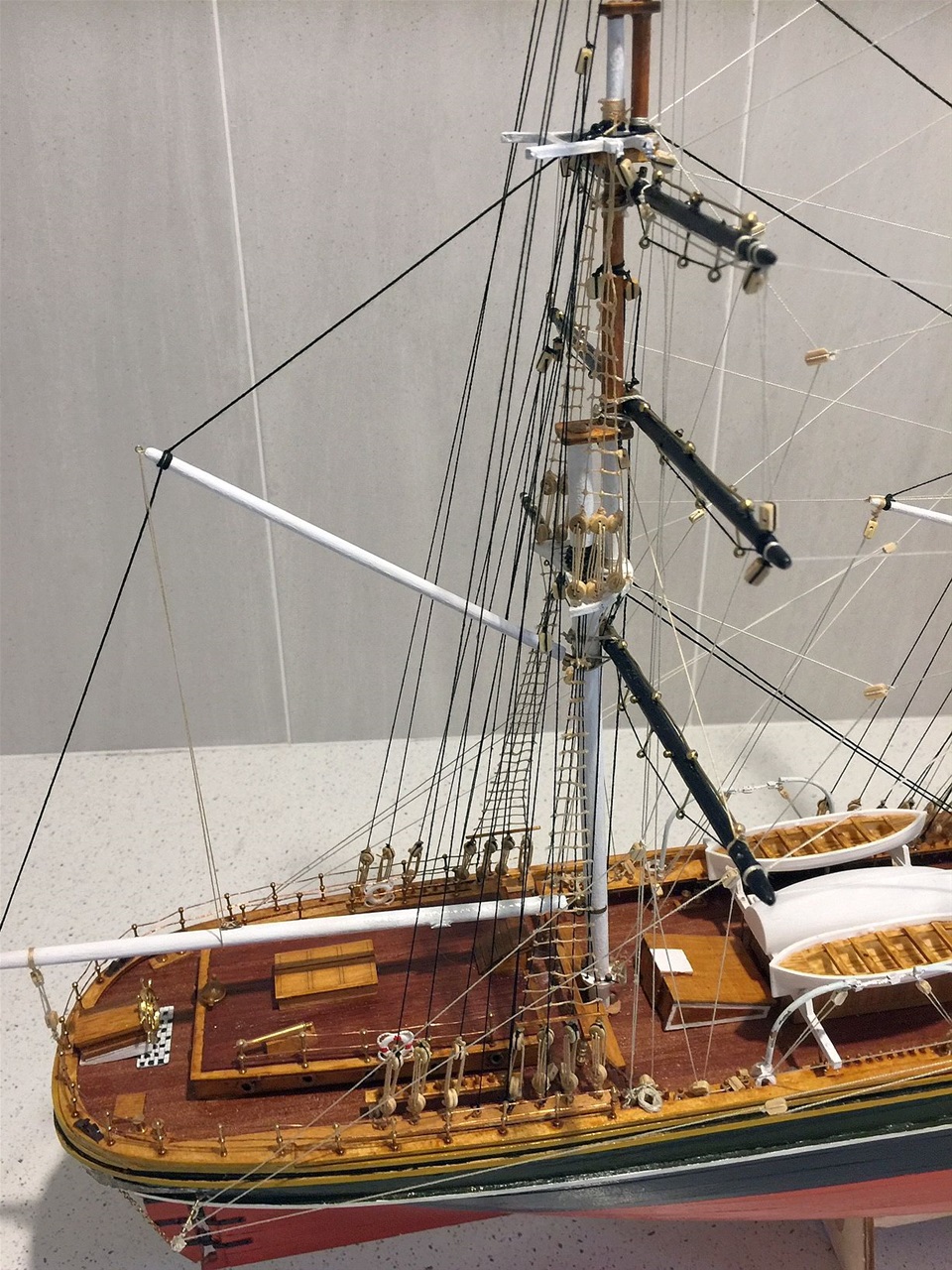
Masts completed and temporarily in place
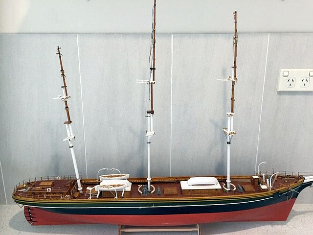
The masts were assembled - from forrard to aft - in the usual fashion. Firstly the lower section shaped according to the widths required at base and upper end - ensuring these fit the deck apertures and the main and other tops, cross trees etc. This applies to each of the three sections in each completed masts.
Similarly, as each section is finished, it is advisable to secure the various fittings as, in the case of this model, there are a number of brass bands and belaying racks that must be sited before total assembly. In addition, this model require holes to be drilled through the topmasts to accommodate specified rigging.
If sails are to be included, all the blocks required should be lashed in the nominated places. In this model, those blocks required for the sails are marked with an 's' while blocks needed without sails are marked with an 'L'
Finally, paint and sealant is applied as specified prior to seating the masts.
Masts aligned before securing
Before bedding in the masts, they must be aligned as best as possible with the final positioning determined with the addition of the standing rigging. Some kit makers recommend securing the yards prior to placing the masts. In this case, it is considered preferable to set the yards after the masts are firmly in place.
Note: some of the topmast partial rigging has been threaded, together with the fitting of the appropriate blocks.
The yards prepared for fitting
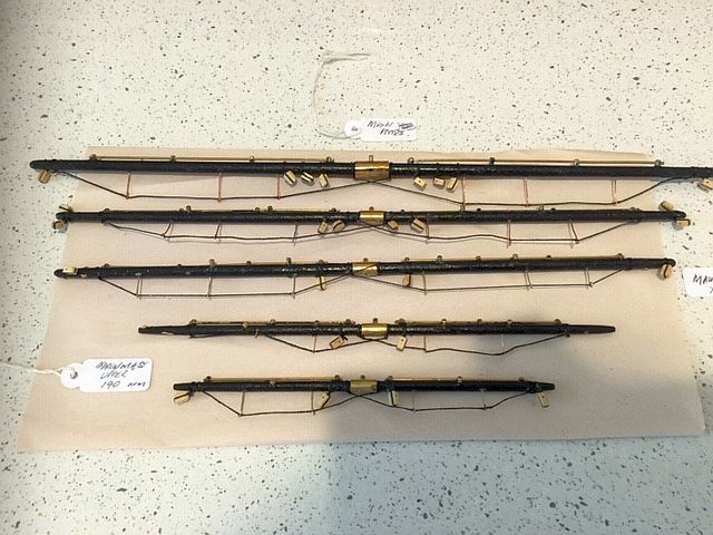
The yards for this model are fairly complex to make and certainly take much longer to assemble than for the average models.
The yards have to be fashioned to shape, as per the masts, with a brass centre piece to which an eye bolt (see below for comment) is fitted and used for reeving the yards 'main' haul. In addition,there are a number of specially designed eye bolts which are mostlry used for the sails rigging. It is desirable to fit these, even if there is no intention of setting sails. Special strengtheners are made for the footrests, from eye pins, placed at intermittent spaces, All these 'special fittings' require either pre-drilled holes using fairly fine drills, or needles,depending on their size.
Again, these must all be prepared before attaching to the masts. The photo shows five of the six main mast yards ready for setting.
Preparing for Standing rigging
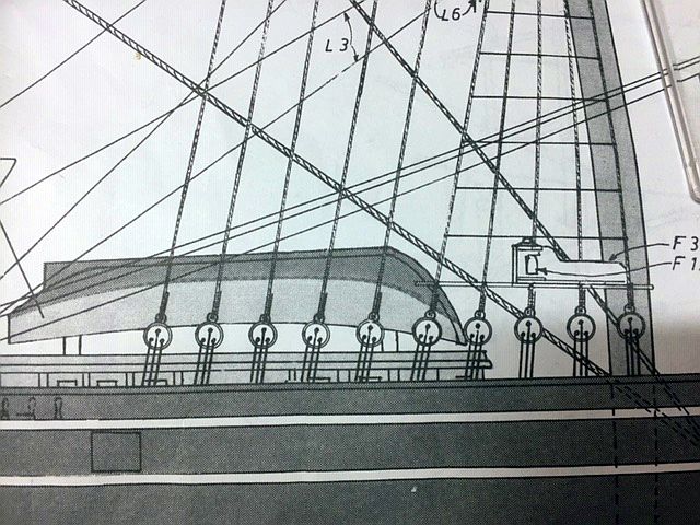
Illustration from plans provided
The plans/instructions for securing the shrouds and back stays are unique to the Cutty Sark - quite unlike any other vessel experienced. They are made fast to eye bolts placed in specific places on an internal platform circulating the hull inside the bulwarks and behind the pre-drilled (laser cut) holes made for the belaying pins.
The lower deadeyes (with very limited space in which to work) are thus almost level with the bulwark tops when lashed to the pins.
The actual top deck of vessel in Gravesend
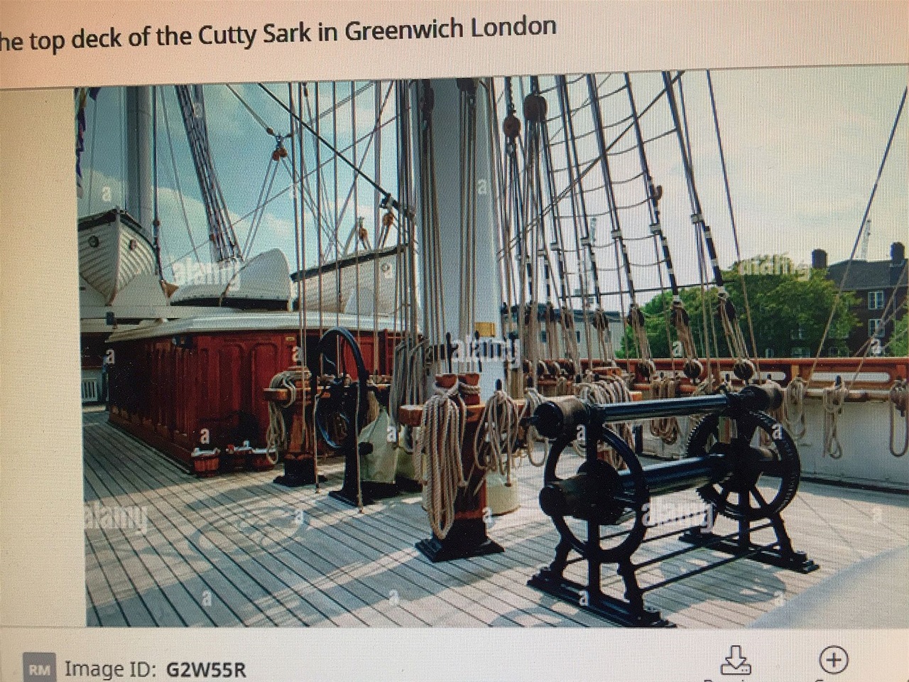
As can be seen in this photo, there is more depth between the internal platform in 'real life' than available in the model!! Hence easier to fine tune the levels there than in the modellers space!!
Unique securing system close up
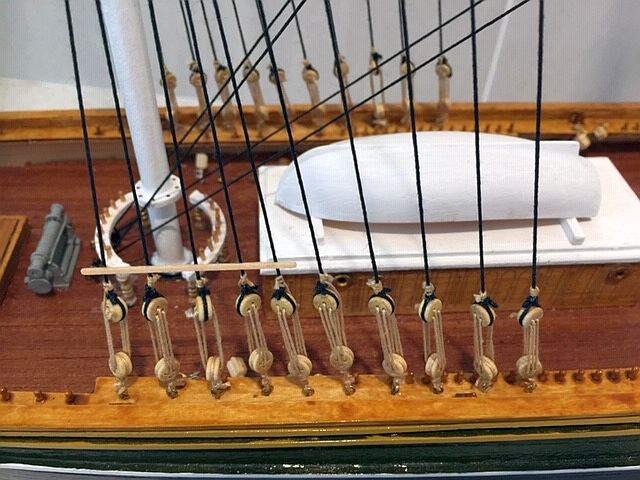
A close up of the unusual system/place of securing lower dead eyes for shrouds/back stays
Foremast, Mainmast and Mizzen mast standing rigging all complete
Now the Foremast. Main and Mizzen are complete.(see close ups below).
The next step is to attach the yards. This will be a slow process as one has to combat the presence of a fair amount of rigging around the outer hull area whilst the yards are secured to eye pins sunk into the decks inside the shroud area. The twin tweezers will be getting a workout
Foremast and Main close ups
Foermast and Main close ups showing showing foremast as being vertical with Main having minor lean aft. Very emphasised in photo but not in actuality !!
Mizzen completed close up
Here the mizzen standing rigging is complete and the booms are positioned and secured. Although not clear in this photo, the mast is inclined to the stern.
All finished except for hoisting the flags
This overall photo of the model shows all the rigging including the running rigging and ratlines on all masts. All that remains is to hoist the bunting and touch up the areas which need a lttle attention
View showing the gilding and ships name with port of registry
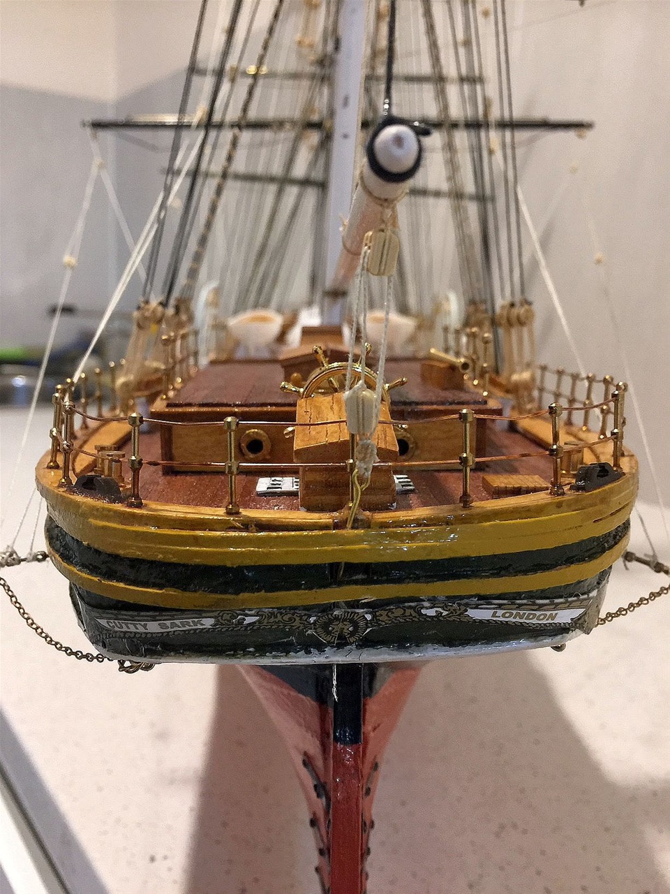
What was understood to be a decal supplied in the kit with ship's name and port of registry, turned out to be film on photographic paper. This had to be cut and trimmed with utmost care before being secured with UTH 'all purpose ' glue rather than other brands as it provided better drying time and can be applied in a 'mere trickle' - very necessary in this case. Copies of the original were made, in case of failure! As it happened the first failed using another glue!
The following photos show sections of the completed model.
View from stern showing all yards
Overall the running rigging took an inordinate amount of time due to some complexity , out of the ordinary and the inability/or impracticality of securing positions as shown in the plans. This made little difference in the final analysis. The yards needed particular attention- being made fast to the masts and it was also difficult to maintain the right tensions as the quantity of rigging mounted. In the finality, a little touch glueing goes a long way!
Stern area showing booms and ensign line etc
Shows the boom's rig plus the ensign hoist awaiting the final touch, the backsays and shrouds.
Foward area including bow structure, anchor positioning etc
Also may be seen the figurehead at the base end of the bowprit. It represents the figure of Queen Victoria but not very noticeable!
The finished product
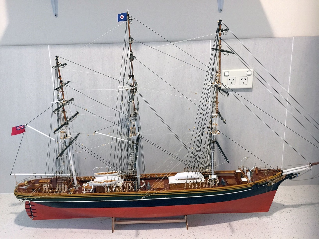
The final photograph taken after touching up the paint work, checking the settings of the yards and rigging and raising the ensign and house flags.
18.7.2022