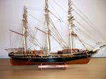
San Juan Felucca
A Felucca at sea
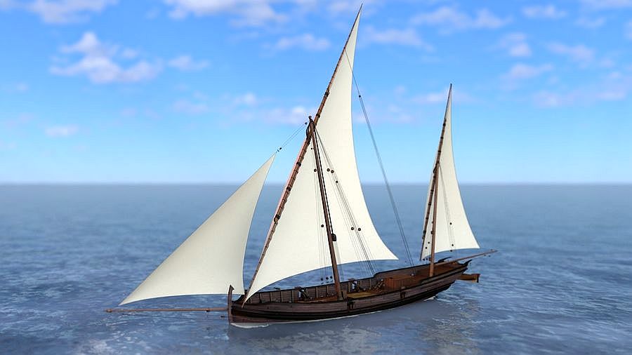
Felucca at sea
Photo from kit maker Occre
History of San Juan
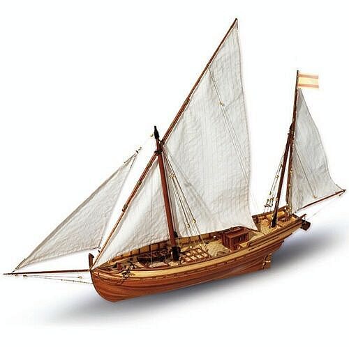
Model of Felucca by Occre, kit makers
History of San Juan, Spanish Felucca
Similar to the Xebec(Xabeque) the Felucca designed vessels were used by the French and Spanish in the Mediterranean Sea by many nations and for various purposes. They both were equpped with Lateen Sails and oars for propulsion. Although they had a narrow floor area to provide a higher speed, they still had a beam to allow for an extensive sail plan.
The lateen rig allow them to sail close hauled to the wind with ease, providing them with an advantage over other vessels, either for defence or attack.
Following the War of Independence, after Spain had lost her American colonies, merchant marine ships all but disappeared from the peninsula, leaving only small coastal sailing boats behind, such as the Feluccas, to re-establish the routes to the Antilles.
Through the Royal Decree issued by Charles III, trade was re-opened with those colonies that remained faithful and it was the Felucca, “San Juan” that made the first voyage.
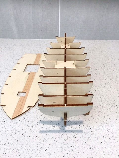
The Model Construction Progress - The beginning 1

Profile view of initial construction
The kit for this Felucca was passed on by a friend, to be made as he was not in a position to do so. The maker, Occre, provide excellent photographs and instructions together with the normal fittings and woods. It is a model suitable for beginners but does require concentration and care to ensure an accurate start is made.
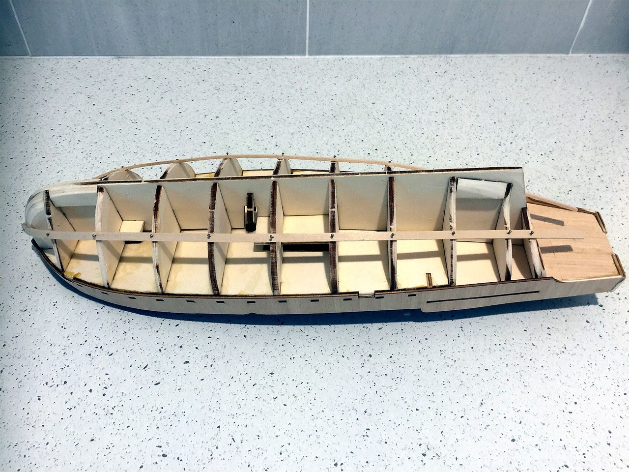
The lazer cut frames and keel parts are easy to remove, with care. They are then assembled and, in order to ensure their correct positions before gluing, it is desirable to have temporary stand made. As is seen in the following photos, thr topsides of the frames must be dead set in line as the main deck must fit cleanly.
Before attaching, the main deck is required to have the decking applied. They recommend doing one side first and the lengths of 8 mms cut and set etc.
Construction Progress - The beginning 2

Showing the alignment of the frames, checked from above as well as abeam.
Also the port side of the deck plate has been started as mentioned above.
Construction Progress - The beginning 3
An eye level view of the frames.
Deck planking complete, stained and sealed
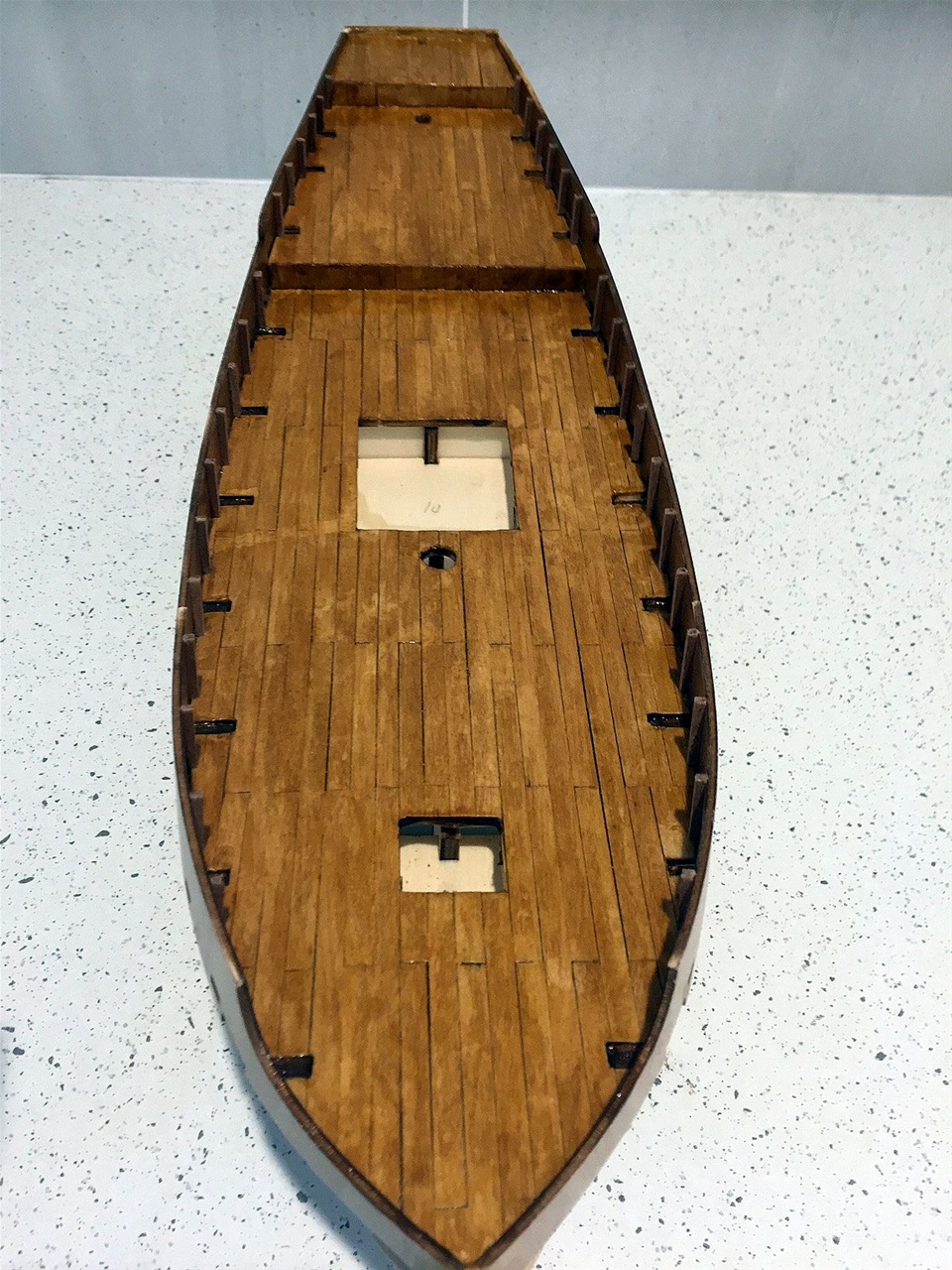
Each of the deck levels were laser cut in plywood and were individually planked, each level being laid in accordance with the cuts of adjacent one. All deck planks were cut to 80mms and laid in brick fashion.
The deck planking was straight forward but suffered from minor stains on the Sycamore/lime wood. A thin maple stain was applied followed by a clear sealant. It may be necessary to apply more later as the stains are still noticeable.
The bulwarks were in two laser cut outs which had to be carefully aligned with the deck line and secured with quick drying adhesive - after minor shaping with the steam iron.
The next addition was the 34 stanchions - 17 each side internally and secured along the bulwarks - made from 2x2 mms Sapelli. These were individually cut with excessive length and trimmed to the bulwark top level when the glue had dried.
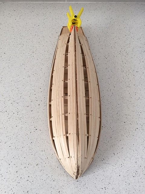
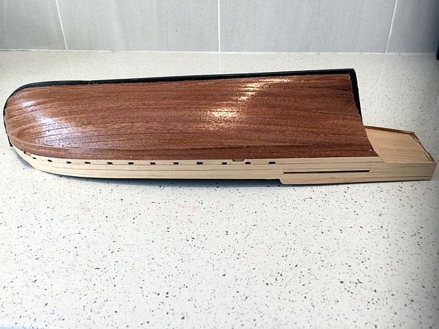
1st hull planking laid

The inner planking is made from 2x5 mms sycamore and the first is placed on either side at the centre line. Thereafter, the planks will be laid alternatively from the centerline down to the keel and up to the bulwarks.
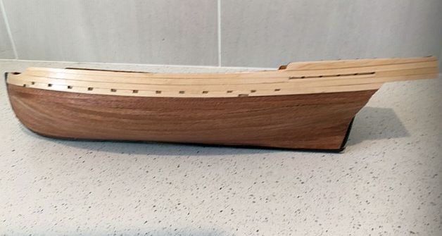
Side view of 1st planking
Showing the side view and overlaps at bow and stern.
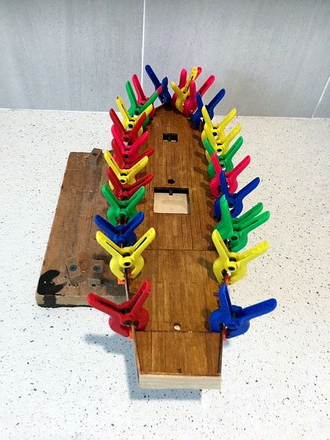
Planking progress 1
This shows the 1st planking progressed to near completion. Note the use of pins, which is recommended by Occre, They also say to 'nip' the pin heads, when the glue is dry and then sand the planking - ensuring the pin heads are not 'proud' of the timbers. In this case, the pins will be completed removed - this being the normal practice followed unless the pins have been 'buried' in the timbers.
Note also that the first planking used is 2x5 mms sycamore - which seems to be somewhat thicker than necessary for a model of this size. It was found the shaping at the bow, in particular, was less than easy. Partially this was caused by the way the keel sections are separate and not - according to Occre - to be fitted until a later stage, thus requiring the space required for the fitting has to be observed with care.
Planking Progress 2

A side view showing also the use of small clips on the overlaps to ensure the ends of the planks are full face and glued on the after frame.
This also shows the amount of planking left which will need shaping and chamfering with precision.
Lining the bulwarks
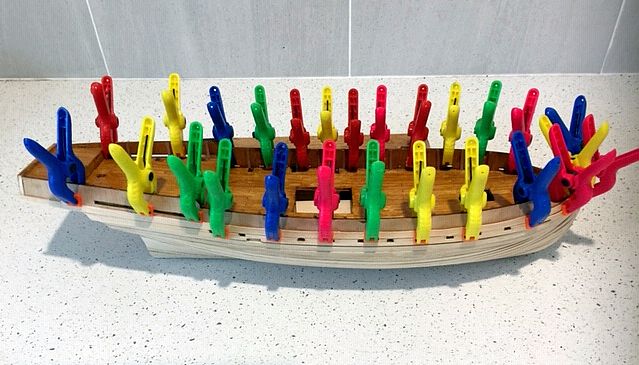
Having completed the hull planking, the next job is to line the bulwarks with 0.6 x 5 mms sycamore timber, being the same timber used on the deck planking. This has to be done in such a way as to identify the positions of the scuppers so they can be trimmed out after lining.
Preference was given to aquadhere, over contact adhesive, using the clips to hold the lining in position for overnight drying. Light steam iron bending was used on the lining which was allowed to dry before attachment.
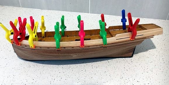
Bulwark lining in profile
This view shows the scuppers having been trimmed out after completion of the respective rows.
2nd Planking complete
The second planking, using 0.6 x 5.0 mms Sapeli timber, went relatively smoothly but - contrary to the kit instructions - the false keel was glued into place (painted black) in order to ensure the first planking laid next to the keel was correctly butted up.
The planks secured from the deckline down needed to be slightly narrowed at the bow, after the first two were laid. Similarly wedges were required in the stern as soon as the planks 'demanded'' ie, when they needed to follow their 'natural' shape of the hull. The adhesive used for this 0.6 thick timber was UHU All Purpose. This glue allows enough time to correctly align the planks when setting - but care is needed to apply just a trickle!
On completion of this section, a good overall coating of sealant was applied to protect against any accidental spillages etc.'
Side view of 2nd planking
Here the alignments can be seen prior to the insertion of two rows of 2.0 X 2.0 mms Sapeli in the white section of the bulwarks - from bow to stern - one each above and below the open scuppers. These need special care in application.
Side 'siffeners' clamped whilst drying
Again this shows the value of using the clamps to hold in the 2.0 x 2.0 'stiffeners' above and below the scuppers.
At this stage the rudder is fitted using the pre-cut rudder and the brass hinges all of which were fairly straightforward.
Most deck fittings in place

In case it hasn.t been noticed, attention is drawn to the bow where an extension to the false keel is now proud of the bulwarks. During the fitting of the false keel, this section above the bulwarks broke away and was disfigured beyond repair. A new piece section was fashioned accordingly but not fitted until the model swas safely mounted on its stand!!
This allows some stability when fitting the deck with the 'bits and pieces' which are now seen in this picture. This is started by fitting 17 stanchions each side followed by longitudinal stiffeners internally around the stanchions.
The individual pieces all need special care due to their small features. For example, the davits which overhang the stern are 4.0 x 4,00 African walnut which had to be shaped with four 1.5 holes drilled to accommodate the lines for the lifeboat. There are a multiude of small parts in metal which require finite painting - with a very steady hand!!
Deck fittings - Lifeboat lashed
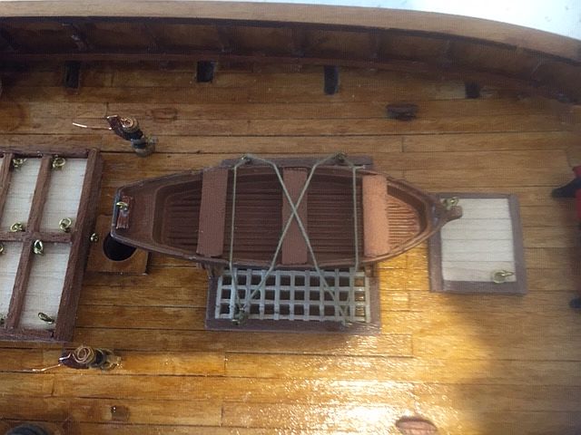
The lifeboat is lashed to cradles mounted on the forrard hatch and secured to the multiple pin heads found in both hathes (see next Photo).
Note the weird pumps just abaft the hatch placed there according to the plans without explanation. The pumps have strange bent wire attachments which presumably are controls.
Deck fittings - the main hatch
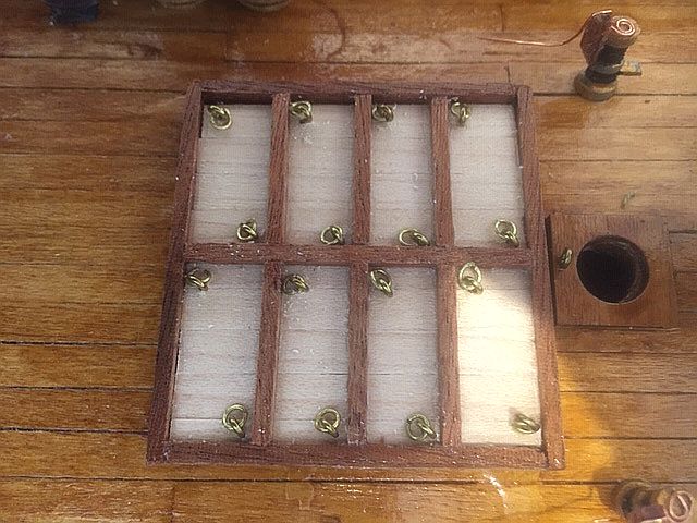
Each section has two sets of circular pin heads fitted with brass rings. See pumps with strange fittings as mentioned.
Lifeboat slung at stern on davits
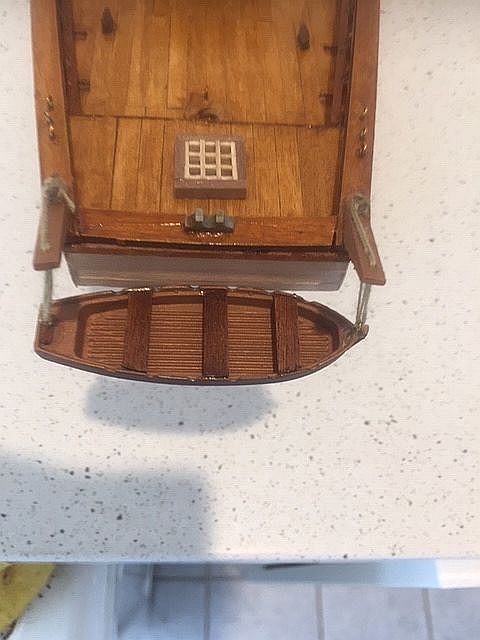
The lifeboat on the stern under davits is hoisted and lowered by hand, we presume, as no other method is apparent.
Masting and rigging commenced

This shows the unique style of masts and rigs typical of the lateen sail requirements on the Feluccas of their time. The main mast is angled forward and a 'floating' boom made up of two sections of 4mms timbers lashed together is attached as shown. Later it will be seen how the sails fit into pattern.
Another view of the forward rigging etc.
Just another view from the port side
Close up of the rigging on the Mainmast
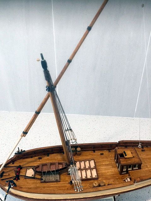
Here it can be seen that the shrouds secured from the top of the mainmast are lashed to the rings on the bulwarks on both sides with a standard block and tackle rig for the lower connection.
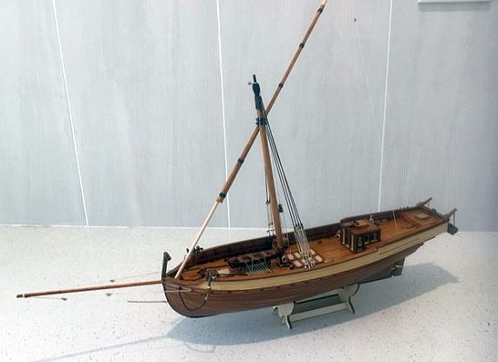
Sails attached and set

Following a great deal studying the diagrams and rigging plans - which showed conflicting lengths of lines and positioning - the masts were sails were set, using data which seemed to fit the best. However, the results didn't exactly match the plans but were close enough to the Occre photo of the model they made. The Spanish flag was the last attachment which signalled the conclusion of the more lengthy project than originally predicted!
Stab'rd side view and Spanish flag flies.

Judgeing by the size of the Main sail and in particlar, its base which almost polishes the deck, it must have been hazardous forthe crew when moving about - especially in bad weather.
Well, the project is now complete. Now it's time to change direction and make something more modern.